PROCESS
OF ANGEL TWEAKING
A small disclaimer note is in place here.
Before opening the amplifier like this, please ask yourself some
questions. It may help you to avoid risk of accident, or damaging your
beautiful amplifier.
1. Do you now and understand Ohm's law ?
2. Can you read the schematics of this amp?
3. Do you know, that DC voltage is 10 x more dangerous for humans than
AC, and even 30 V DC can be lethal if the current flows via both hands?
Do you know that there is 900 V DC in the Angel?!!!
4. Are you aware, that capacitors can store the voltage for MONTHS
AFTER DISCONNECTION?
5. Have you ever done some soldering project that actually worked
?
If one or more answers are negative, please think again if you want to
go there. This is the last moment to stop... ;-)
I think that the power stage of the angel is good, there is nothing to
do there.
The input stage is easy to work on, and it brings phenomenal
improvement.
I suggest to get first the right parts and print the schematics which I
provide. Get the tools you will need (just soldering iron, clippers,
pincette and flux solder.
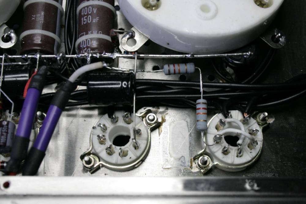
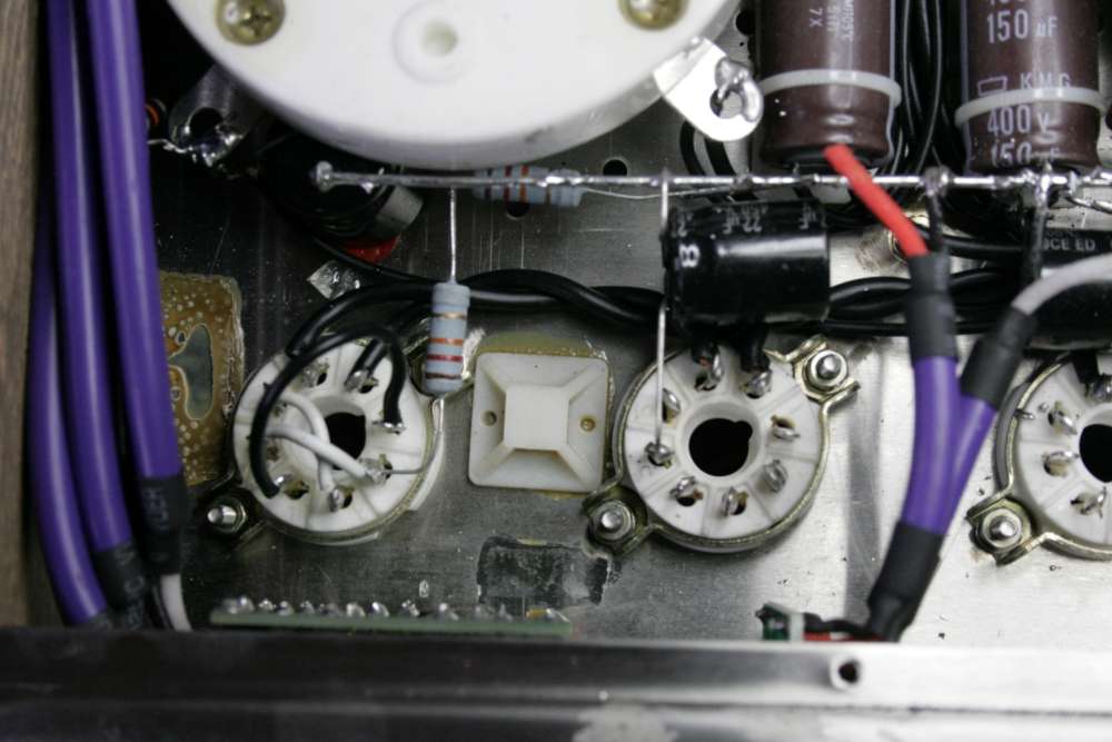
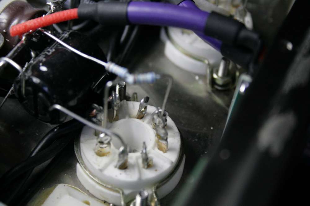
First, remove all components except the shorting white wires in sockets
V1 and V4.
The last part that stays is the brown capacitor (two of them) marked
150uF/450 V positioned slightly "above" the earth bar, between sockets
of V2 and V3.
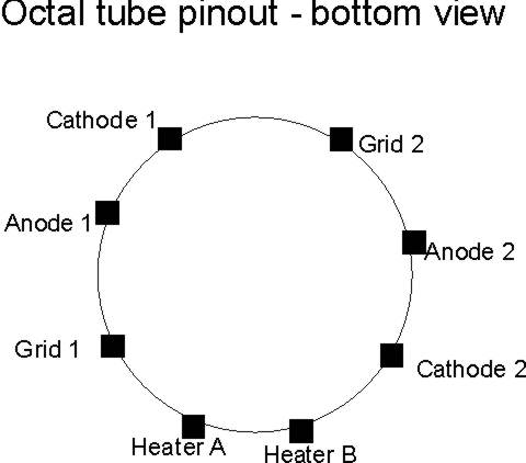
When looking inside the Angel, this pinout will be rotated 180 degrees,
with two black heater wires visible on 12 o'clock at legs 7 and 8.
Clockwise from them there will be gridA, Anode A, Cathode A, and GridB,
AnodeB, CathodeB, being respectively legs from 1 to 6.
Everything is removed except the 150 uF cap (brown ones- main supply)
and V1 and V4 anode resistors and V2 and 3 anode caps (22uF black ones)
The positive leg of the brown 150uF cap is the starting point - main
supply to the four tubes.
The extreme left and extreme right tube (V1 and V4) are called driver
tubes. Before the signal goes to driver tubes, it enters from trhe RCA,
goes by long cable to the input selector, then to the potentiometer,
and then it arrives to the end of short cables visible on photo above.
The amplification starts on tubes V2 and V3 - being so called input
stage. It amplifies the voltage of the signal by some 40-50 times and
the circuit is SRPP like the lampizator.
The high volt signal then goes to driver stage, which is not lampizator
but parallel triode with resistive load. Two triodes must increase both
the voltage and driving capabilities of the circuit, that's why the
triode is a different tube, with 10 x more current capability (lower
amplification and lower output impedance) and on top of that it is
paralleled to get double current and half impedance.
Between all stages - input-driver and driver - power - the signal must
remove the DC component that's why we use interstage series capacitors.
These should be replaced because the originals are a) too small and b)
too low quality.
While the first cap can be a little smaller in value, we can get away
with cap as small as 220 nF and voltage needs to be at least 160 V, the
second cap must be much bigger, 1 uF minimum, better even 4 or more. It
must also have high voltage rating - 600 VDC or more. That is a
criteria hard to meet. Or at least expensive.
The caps should be from metalized polypropylene, or better metal foil
insulated with polypropylene, or best - paper in oil.
I use Arcotronics MKP and it works fine.
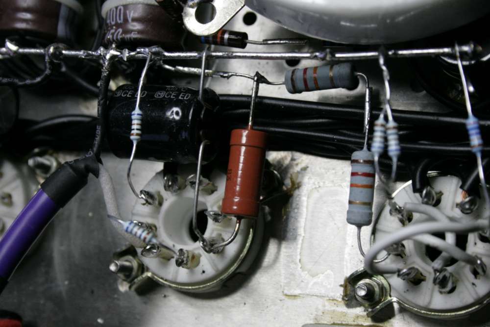
The two anode resistors to V1-4 (12 k both in series give 24 K) can be
changed for just one (12K) or better replaced with 15K
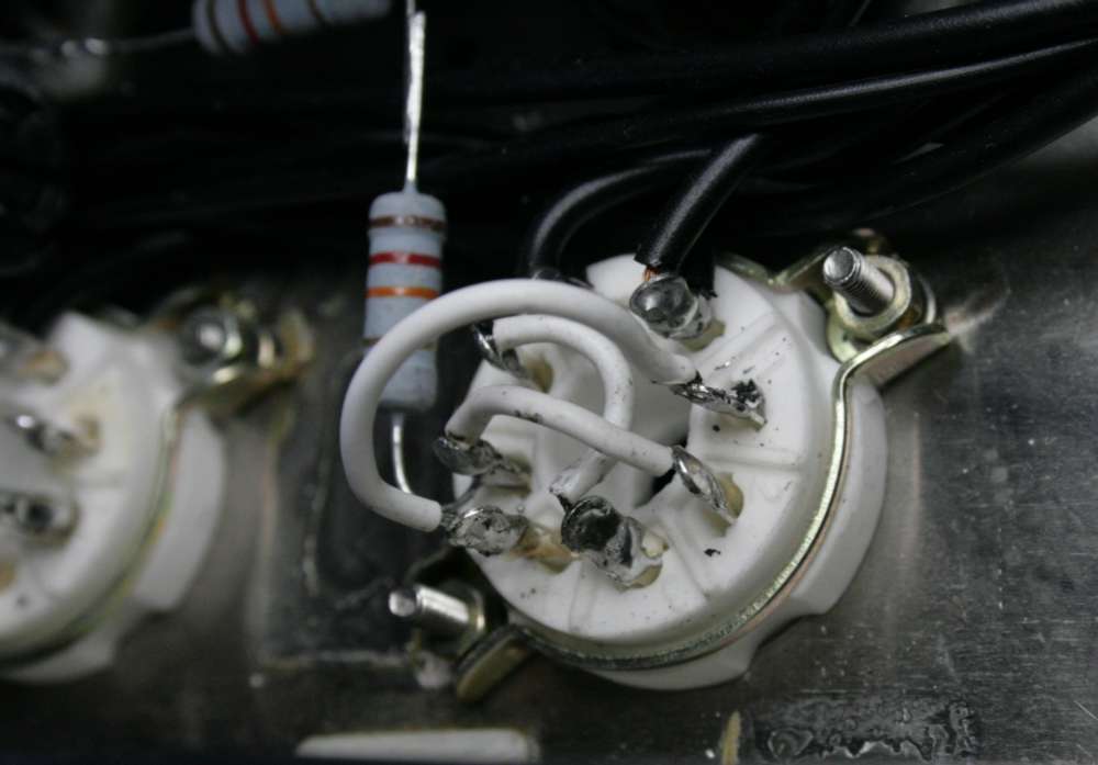
In V1-and 4 add a shorting wire between grids 1 and 2. So all legs are
connected: two grids, two anodes and two cathodes.
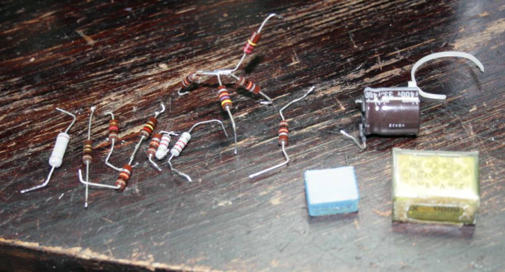
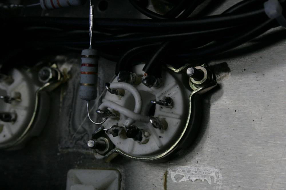
Parts removed

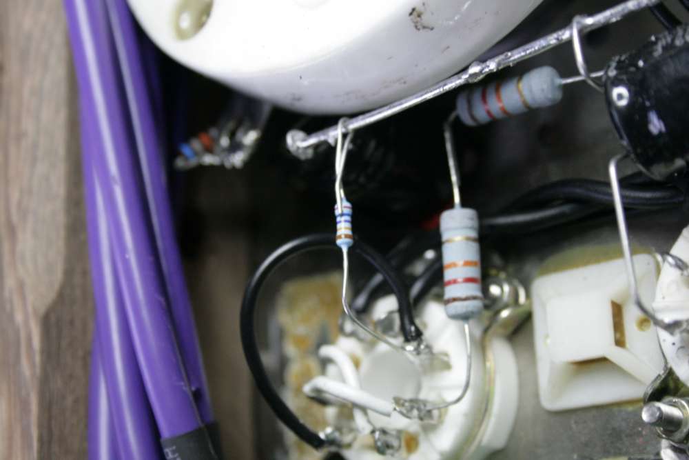
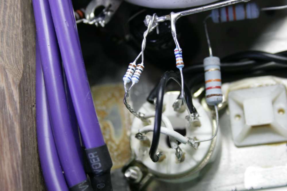
In bias circuit to 845 there are 3 remaining resistors. Remove
the last one
(top of the three in the picture) and solder the two back to 845 grid.
Left channel cleaned.
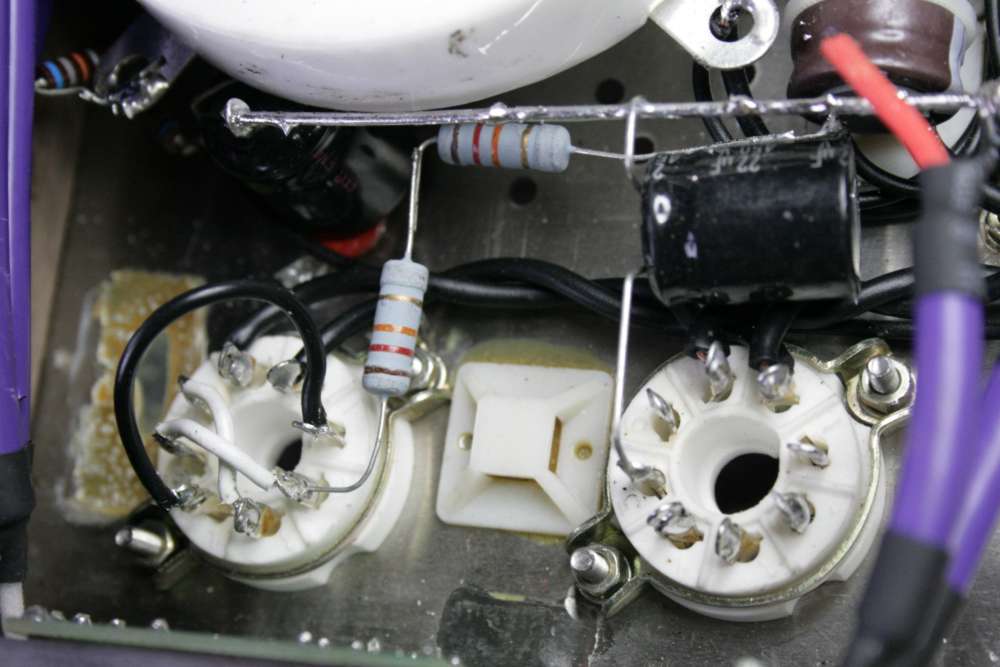

Parts to the dustbin.
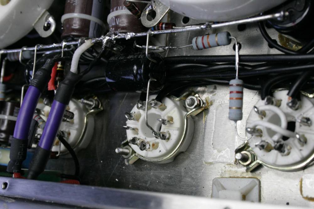
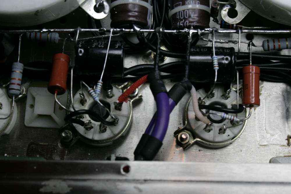
Add a driver stage 250 K grid resistor.
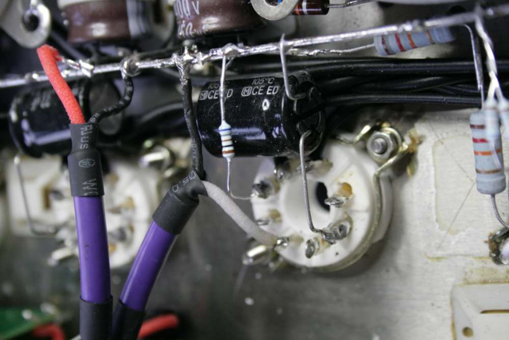
Same thing on the left channel (right side when upside-down).

Twisted pair of resistors are cathode 340 Ohm resistor (paralleled 680).
Later I published an improved circuit with 15 K anode and 1,2 k cathode
resistors.
Same in other channel. Twisted = cathode, single = grid.
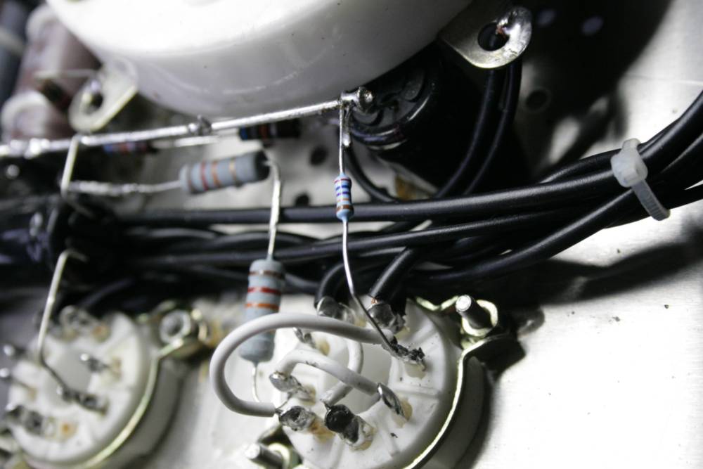
Add input tube V2 and V3 cathode 680 Ohm.
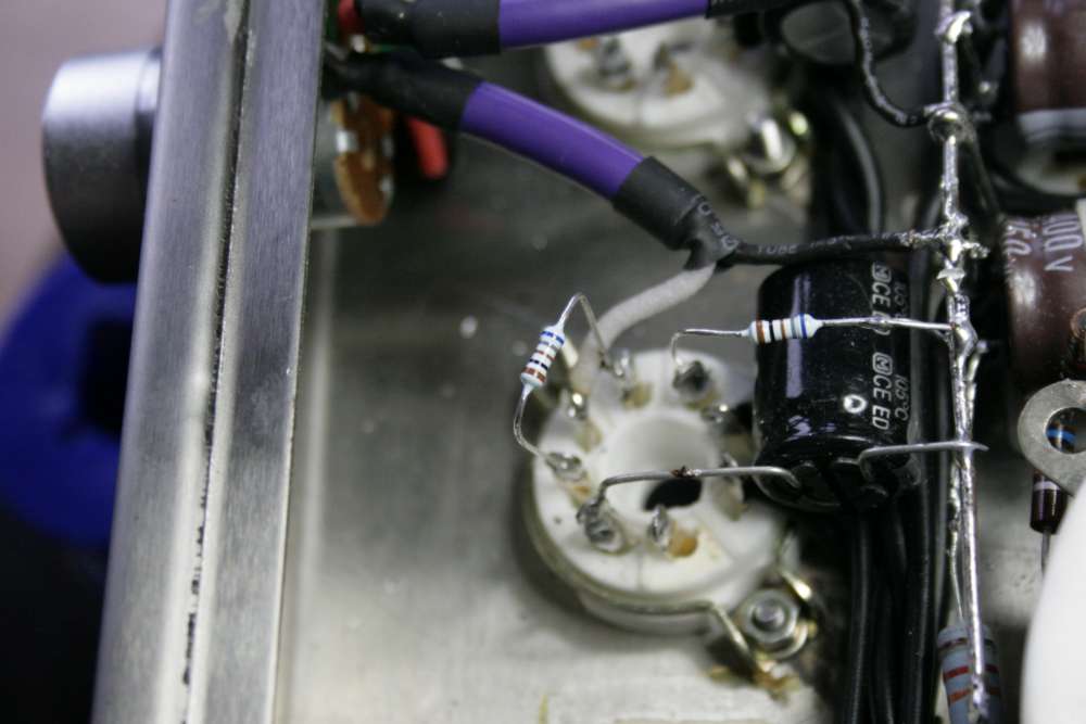
Add a 680 Ohm between cathode
and anode of SRPP input circuit.
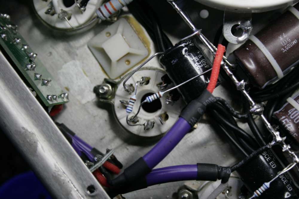
Add
a V2-3 power supply resistor of 47K (red one). This works OK for the
6N8 tube. If you want to keep the originally supplied 6N9, the supply
resistor should be 60 K or close.

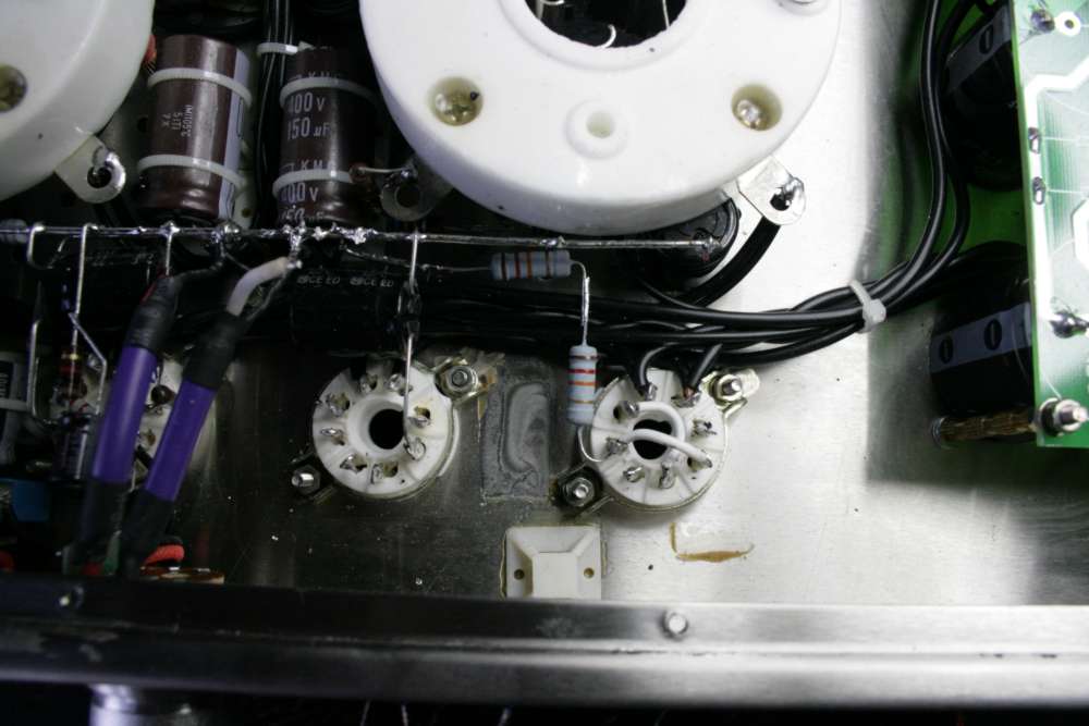
Input tubes V2 and 3 ready to rock and roll. The signal cables
connected to respective grids directly.,
Please note, that for the purpose of cleanness of the soldering job, I
use two tube halves in mirrored application. So on one channel one grid
is an input, on the other channel - the other grid. The two triodes
inside one tube are identical anyway.
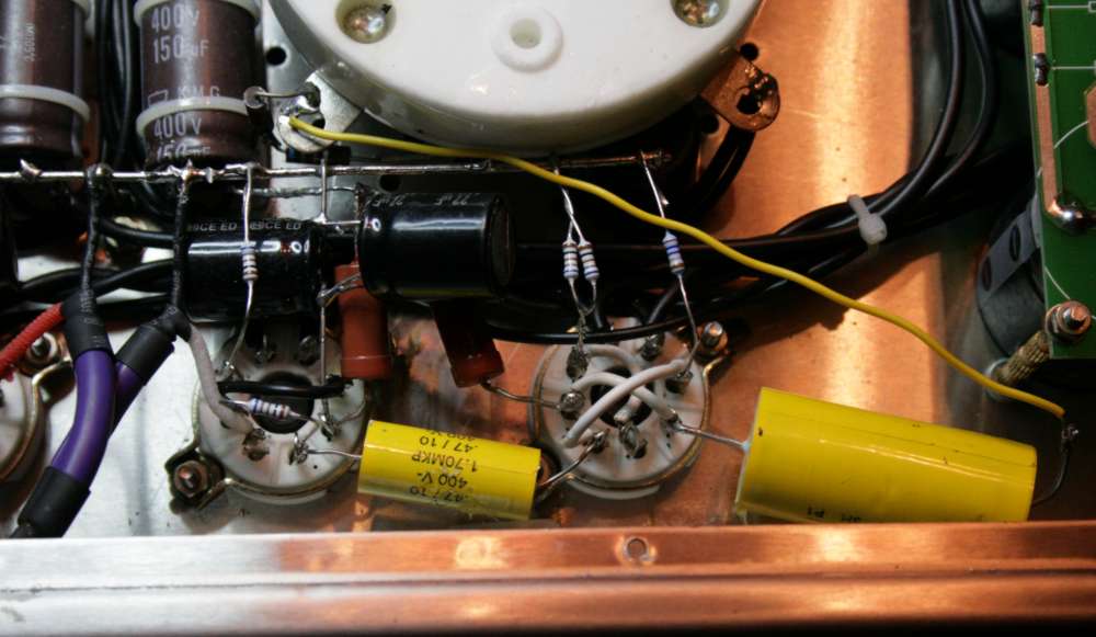
Adding interstage decoupling caps (0,68 to 4 uF will do)

Angel ready to sing. Note the driver tubes NOS JAN from USA
(black ones)
TESTING:
After connection of power, be ready to unplug the amp if something
smokes. You should start without power tubes, just the small ones.
Maybe to avoid damage - start with one tube and one channel at the time:
Measure the voltages with DMM set to 1000 V DC:
1. main supply of our circuit - brown cap 150uF/450V = result around
400 V
V1 anode: between 200 and 250 V (230 optimum)
V1-V4 all heaters - 6,3 V AC or DC, +/- 5%
V2 - one anode - 220-300 V DC, second anode of the same tube - half of
that. Optimum is 250 V.
All grids must be at 0V
Cathode: the cathode resistors are for self biasing of the circuits,
they provide voltage drop proportional to the tube current and resistor
value. The higher resistor the higher voltage drop the less the tube
conducts (grid closes).
Optimum current should be:
for V1 and V4 - between 5 and 12 mA (so if the Cathode resistor would
be 340 Ohm, the optimal 10 mA would result in 3,4 V DC on the
cathode. This is equivalent to -3,4 V DC grid bias.
For the V2 and V3 - the current is smaller, between 1 and 2 mA. So 1 to
2 V across a 1k resistor, or proportionally less across a 680Ohm one.
After
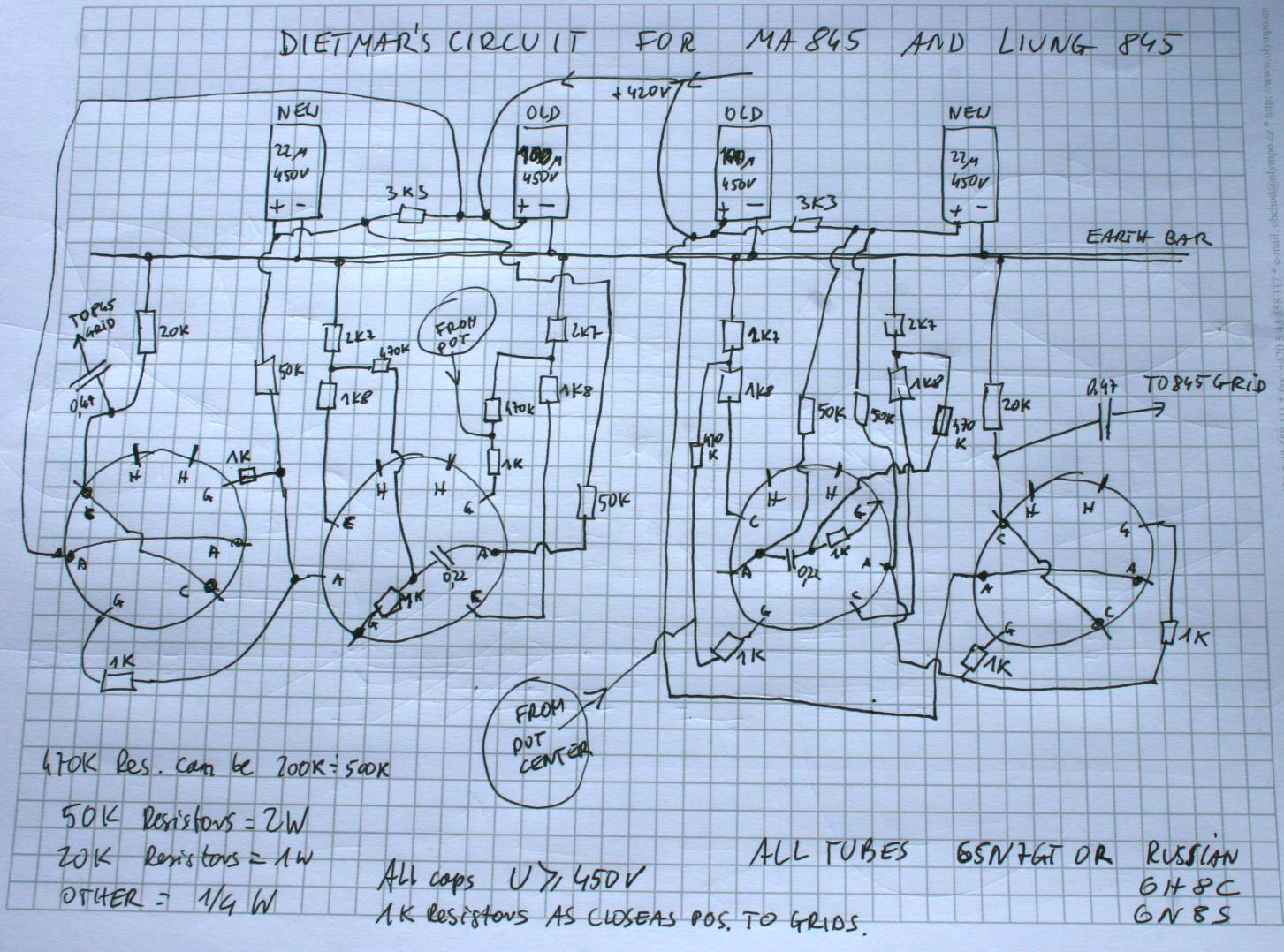
4 months - I present the latest schematics. I like it best.
SCHEMATICS
LAYOUT
AND HERE IS a
special schematic - supposedly much better than mine - from a very
nice and knowledgable man from Linz Austria - Dietmar Gerhold whom I
thank for sharing with us his good job.
Here is a
detailed description.
I tried the schematics from Mr. Dietmar and I must agree. It sounds
better on bass, on width, on height, on depth, on details. Everything
is stable. There is no hum, no noise, no overheating of parts. It is a
top solution for today - June 14 2008.
I departed from the supplied schematics here and there by no more than
10 % because I used parts available. Apparently everything is OK.
Current below 4mA, voltages plus minus the same.
I recommend this mod over my own proposal.
I am ready to forgive the Austrians the match against Poland.
BACK