We should particularly stay away from Op-Amps commonly used in almost all audio devices.
The general rule is that the more simple the schematics - the less distorted sound we get. Lampizator, however sophisticated and refined it may be, is only ONE active amplification stage. One active device. (idea of connection)
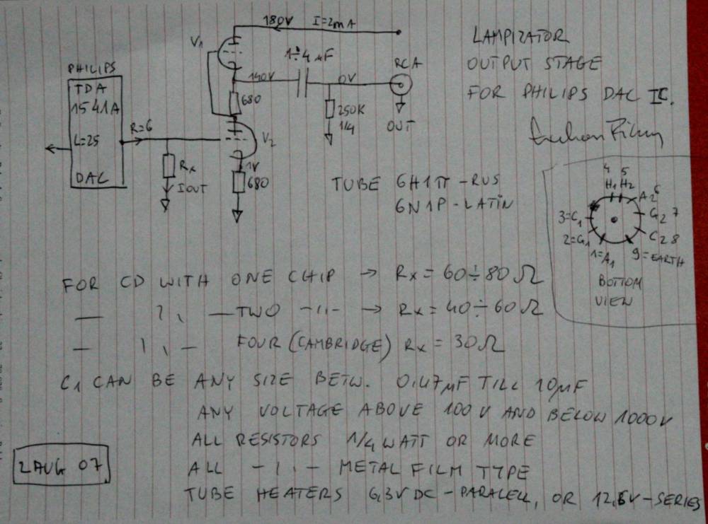
The schematics was suggested by my tube technology guru Mr. Evgenniy Kreminski from Lvov, Ukraine, who spent his life refining tube schematics for various applications.
The schematics is a triode amplifier, anode follower set-up, with active dynamic anode load instead of the commonly used resistor. THIS IS NOT A CATHODE BUFFER as many people wrongly believe. I think it is a variation of a well known SRPP scheme, refined to the limits.
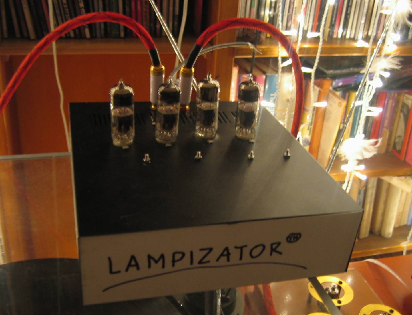
The tube used is the best, small signal, nine pin triode known to me - the super mighty 6H6P (in latin it is 6H6P).
There exists a variant of this tube known mainly from BAT creator - Mr. Victor Khomenko, - the 6H30P. This "super-tube" is impulse variant of 6H6P. But in all aspects of musical amplification the 6H6P is superior because it has been designed especially for analogue, not impulse signals. Compared directly to 6H30P - the analogue variant is more liquid, more real, more analog-like, more musical, and more everything else.
This Russian tube is very powerful. It is double size compared to typical noval tubes and it can put out about 8 Watts of power and swing up to 350 V.
This is ladies and gentlemen the KING OF SUPERTUBES. (see separate section about 6H6)
My schematics can work very well even with anode voltages as low as 50 V and the amplification factor is around 10. Of all schematics we tried, including triode, paralleled triode, cathode follower triode etc. - it has the most dynamic and spacious sound.
I run this schematics at 160 VDC power supply, with 12,6 V - two tubes in series or parallel 6,3 VDC heaters at 0,7 A per tube. The anode idle current is circa 5 mA but at the cost of dramatic power supply size increase - it can be as high as 20 mA. This tube puts HUGE demands on heater circuit (3 A for balanced 4-tube schematics) but the result is well worth it.
This tube can be used in all E88CC or 6922 circuits because it has the same pin-out (heaters between 4 and 5 not between shorted 4-5 and 9).
If you can substitute this tube in your gear - remember it needs double the regular heater current (commonly 300 mA for small tubes).
I use the most simple power supply: the toroid trafo (30 VA, minimum 20 VA) with CRC filters, using huge capacitors in anode, capable of playing for 4 minutes after disconnection of AC !!!
I use simple diode Graetz bridges for rectification, you could experiment with HEX-FREDS etc or even tube diodes.
Both channels and both phases need just RC splitter to get their supply of anodes - no need for separate secondaries or transformers. I detect NO problems with cross talk or stereo separation and sound stage geometry. RC is enough.
Before anything else, I study the schematics of the beast under evaluation
For the assembly I use standard decent parts - no exotica which is unnecessary. Metal film resistors, brand name electrolytic caps with 105C ratings, standard hook-up twisted wires, polypropylene decoupling DC caps and occasional ferrite rings. The current and voltage ratings are respected with at least 100 % safety margins. This schematics is virtually indestructible and should last a lifetime. Tube life should be around 5 years.

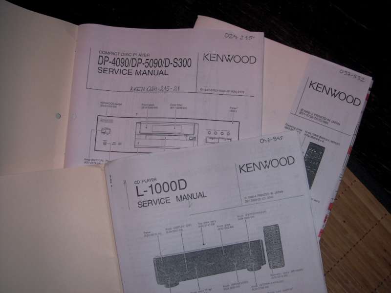
To give you an idea what the lampizator replaces, I included the schematics of a very good high-end CD player - Kenwood 1000D output stage.
The triangle symbols represent op-amps - cheap and shitty amplification chips. They are used by the lazy engineers who use their school knowledge to build standard easy schematics.
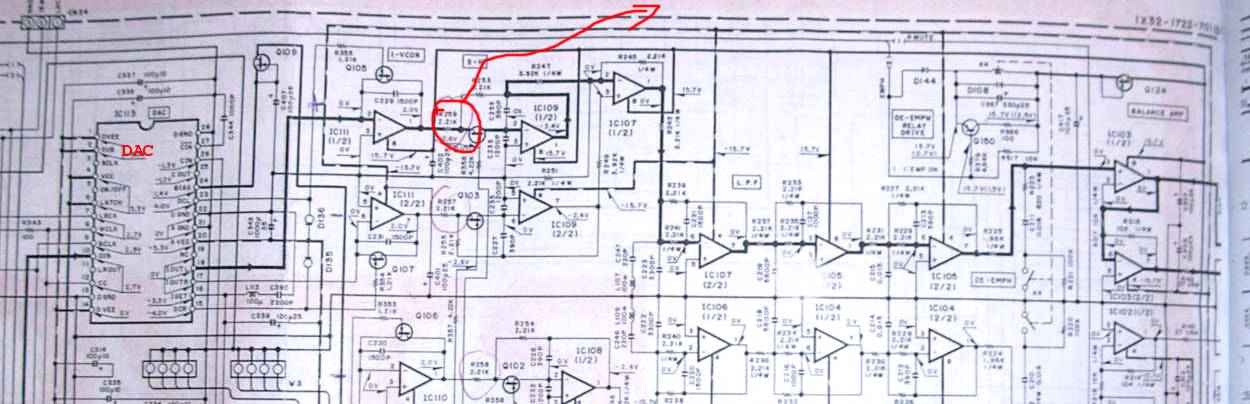
The two vertical rectangles on the left are DACs (Sony) and to the right of the dacs is the UGLY OUTPUT STAGE.
Below I show the signal path from dac to chinch sockets:
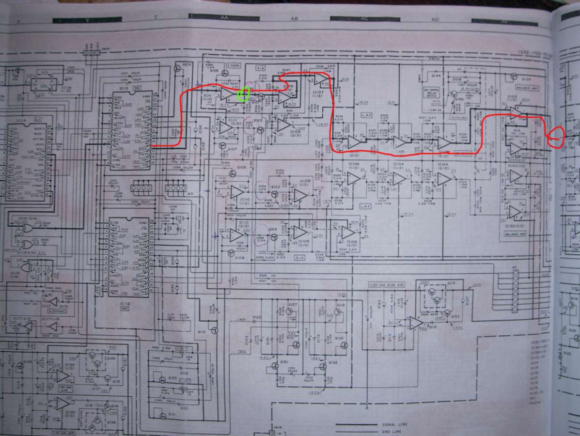
There is 6 op-amps before the signal reaches the output sockets. Plus tens of parts around. The green circle is my tapping point for lampizator.
Just look what is inside of each op-amp. I enclosed so called equivalent schematics of just one half of a "triangle" op-amp. Second half is symmetrical mirror equivalent. Each "K" shape represents one transistor (which we are supposed to hate). There is 40 transistors in this simple op-amp !!!
There are over 30 other parts per phase per channel, so we end up with 6*40 plus 4 * 30 =360 parts in total per output stage and that's not counting the power supplies and regulation. All that crap is redundant and we cut it away.
Ideally, the DAC chip should have a transformer between it's current output and the tube grids.
Just like this one:
SOWTER
This expensive transformer (70 GBP per piece) can be avoided if we use a passive conversion by means of one small resistor. This solution is good enough.
This is the datamining page of mine: DAC chip data-mining