Snip It - modifications for the begginers

(and the tube-haters)


Well, the tube modifications may not be for everyone.

It may not be your cup of tea.
It may  repell you for no reason at all.
Some people will say that they slept through the Ohms-Law lesson.
Others will complain, that the tubes are not true, that they color the sound with pleasant 2-nd harmonics.
Others simply can't be bothered.
Someone may not have the guts to be so radical.
Last but not least - someone may not afford the lampizator job - that is understandable too.

The good news is that we can make HUGE PROGRESS without any tubes

Here will follow simple straightforward recipes for four great sonic improvements using just a pair of snips with occasional help of the soldering iron and a meter.

So lets do it folks! Lets SNIP IT !!!


I can see 4 important areas of improvement that are totally cost-free and take just minutes, plus they are all easily reversible.
And the result is 100% guaranteed every time, unlike some hard-ball mods which for some - may be questionable.

SNIP ONE: CD output filter.

The big secret that I am about to reveal for free (that's why I am a self proclaimed Prometheus, remember)  (by the way, I don't know if the eagle will ever eat my liver, so I am trying to destroy it myself with red wine) is that every budget CD player that I have ever seen - and by that I mean a player lighter than 10 kilos or cheaper than 400 Euros - has OUTPUT FILTER CAPS. These are two small brown (usually) tablettes nearest thing to the output RCA.
This looks like this:


The HF filter caps in AKAI CD-55 player - marked with red dots.


This is Technics SL-700 player with two blue capacitors.

zero dac
This is otherwise excellent ZERODAC with two 220p capacitors nearest to the RCA's

nakamichi CDP2-e
Otherwise excellent Nakamichi CDP2-e with snipped caps.


I think you get the idea.
The purpose of shunting the signal to the ground just before output is that it shall ground (kill) high frequencies which are trebles, midrange upper harmonics, and some noises too.
The idea behind it was that the designers were forced to play the SPECS game. Every CD in the 80-ties and 90-ties was being compared to the others by specs. And because the spec of CD - when it was introduced back in 1982 - categories were derived from the cassette, the LP, the tuner and the reel to reel, they were quoting signal to noise ratio (S/N), wow and flutter, and dynamic range. All completely meaningless when applied to CD. But to be ABSOLUTELY SURE that the CD does not produce ANY noise, they sacrified the trebles.
I mean - the CD was supposed to be PERFECT as compared to noisy LP and tuner and cassette. So IT COULD NOT HISS, NO MATTER WHAT !
Nobody blamed these CD players for having no trebles and no "air", but if it hissed with ear to the tweeter - boooooo! That was a no-no. No good for CD !!!!

Anyway, we can now call these engineers names like morons, idiots, audio-terrorists - enough said. What we don't want is to spread hatered, we want to snip these caps out and enjoy for the first time the REALLY OPEN SOUND.
One - two - three - SNIP!


Number two - Amplifier input filter


Number two is a really easy one. Some paranoid engineers from AMPLIFIER department did not trust their colleagues from CD department and so they added similar caps at every INPUT of the amp. Just in case.
So just open the amp, look on the small PCB where the RCA's are mounted, and identify a pair of small caps near them.
SNIP them as well...

Now you will begin to hear niuances and some air too.

The real ear-opener is when you do it on BOTH - the CD and the amp.
And just imagine, you were just about to go to your very friendly and helpful dealer, who never let you down before, and ask him for recommendation for an IC cable which would make your system a little brighter and more airy. You were prepared to spend 300 Euros on a good silver IC.


The MARANTZ amplifier after the input PCB has been cleaned of the filtering caps.


The removed caps.

Do you see what I mean ????


NUMBER THREE - CD output stage


This is becoming somewhat more advanced.
We will BYPASS the entire output stage of the CD player (filter capc included) which is useless and unnecesary, as explained elsewhere in my website.

The output stage is something which is mandatory and unnecessary at the same time. Don't ask why. This stage is a waste of time, waste of money, waste of space and waste of music as well.

Lets consider two scenarios:
A) The DAC chip has voltage output : we will find the V out R and V out L legs of the chip and wire a cable from that point to the newly installed (in 10 mm pre-drilled holes) RCA sockets.

New RCA's are a must. I pay for mine 2 Euro per pair. The old openings are just perfect size - diameter is 10 mm.
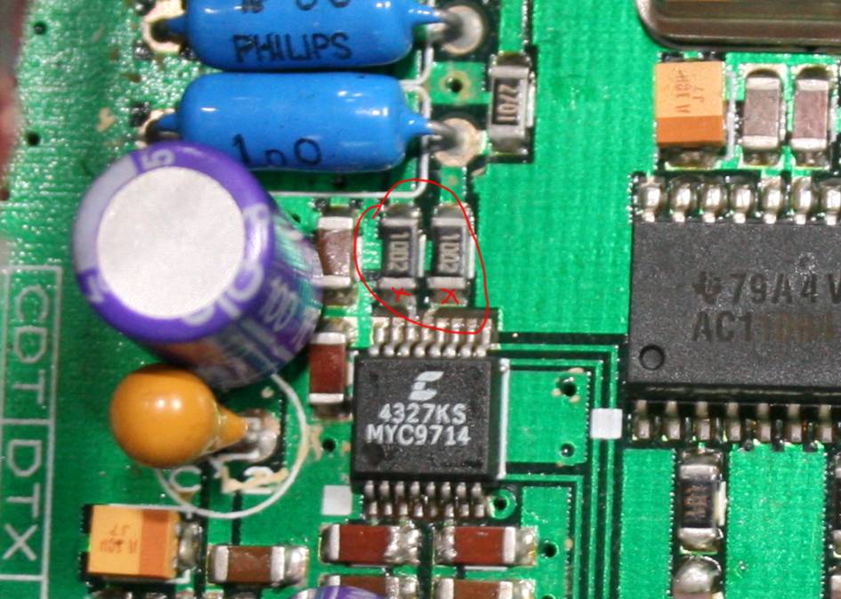
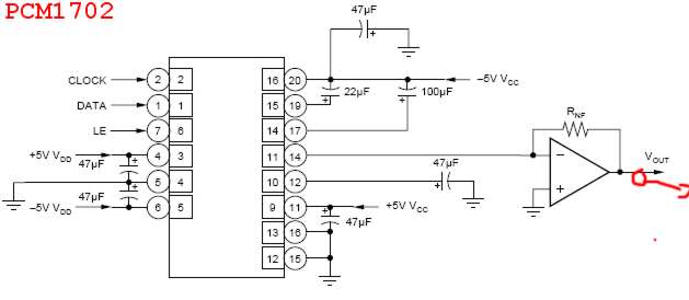


The wire must be connected to the RCA via a foil capacitor like MKP or better paper in oil, value of capacitance between 0,47 and 4,7 uF. Voltage is unimportant.

So first we go to www.alldatasheet.com, dig out our dac chip, download the PDF, read it, find the legs etc.
Then find the respective legs in the real life - on our PCB.
Then solder your wire to first point AFTER this leg to avoid damaging the chip itself by heat.


resostors smd - with red X soldering signal source points


Then CUT the remaining track by means of scalpel-cut or by lifting a resistor or something like this.
Wire the wire to RCA, sit back and enjoy.
Note that the caps are necessary to de-couple the DC voltage component present on these dac legs - usually from the range between 2,4 to 3,5 v DC.

This bypass is giving us the purest possible sound from a given configuration. We are eliminating usually betweem tens and even hundreds of electronic components which play the role of muddying the sound.


In SCENARIO B - where the DAC chip is a current output type - we can't do such simple bypass, but the one we will make is simple enough.
So we identify the NEAREST op-amp to the DAC - usually a pair.
Then we must determin, which type of op-amp they use - dual or single. (usually dual because it is cheaper).
In single opamps the input is leg 2, inverted input is leg 3, and output is leg 6.
In dual op-amps - the input one is leg 2, inverted one is leg 3, and output one is 1.
The second half is input = 5, inverted input = 6, output is 7.

Now backtrace the signal - which leg connects to the DAC output. Say we have a dual op-amp, we trace that the DAC leg 6 (like in TDA1541) is wired to opamp leg 2 , so op-amp output is leg 1.
If the DAC was wired to leg 5, output would be 7. If the op-amp was single one, the DAC would have been wired to leg 2 and output would have been leg 6.
Easy inn'it?


ABOVE - The new RCA sockets and MKP Arcotronics caps in bypass of a player.


PICTURE: Single op-amp


op-amp in CD player

Picture: Double op-amp

opamp


Double op- amp applied as stereo


leg 11/14 is Iout


Anyway - we wire our signal from FIRST AVAILABLE op-amp OUTPUT to the RCA via same capacitor as in scenario A,  so the Current Iout signal is being converted to V out by so called "half op-amp conversion". So after the first opamp the scenario B becomes A again. The difference is that we CAN NOT cut off the existing following path because it contains the local feedback loop.


Picture: signal pick-up point.

tda1541A Mod

Picture: different signal pickup point in TDA1541A player.


OP-amp modification


a good example of very succesful job is here:

Cambridge DVD89 - a surprisingly great player that does movies too. cambridge DVD


THE SNAGS

now it is perhaps a right time to mention the snags, the things that may go wrong.
Some DACs more than others have some residual digital square-wave byproducts of conversion process mixed into the music. This is being filtered in the analog domain after the signal leaves the DAC by means of op-amps with heavy capacitive local feedback crearing a firewall for high frequencies.
Some DACS do not need this, some - do need a LOT of filtering.
In particular, Sony DACS CDX / CDA need filtering, as well as JVC, Pioneer, so I drew the conclusion, that the Japanese school of conversion is noisy, and USA/European - deals with this artifact inside the DAC.
Burr-Brown, Philips, Wolfson , Cristal Semiconductors, Analog Devices and Cirrus Logic are all very clean and silent DACS.
Shall you hear any problem with  the "cricket in a tweeter" and it bothers you, I suggest to experiment with passive RCR filter. Use the filter discretely, better to under-filter than over-filter.
I suggest to choose a signal stealing point from the DAC, add R=1K in series, capacitor 1nF - 10 nF to ground, and again - a 1K resistor.
This should bring the noise do a level acceptable from listening seat. Of course if you crank the amp all the way and put the ear to the tweeter - you will still hear the hiss. I say - be NORMAL and go back to listening.


NUMBER FOUR : AMPLIFIER INPUT STAGE ELIMINATION


Number four gets even more tricky but the reward is well worth the effort.
I am talking about integrated amplifier INPUT BYPASS.
If our amp has tone controlls, input selector switches, balance controll and loudness - we want to bypass all that.
In case of my favourite DUAL CV40 amp (made circa 1969) there is a superbly clean and simple power stage preceeded by VERY complex input board..


SEE THE SCHEMATICS HERE
Just lift the left leg of the capacitor C21 and connect the input signal from RCA straight to the lifted leg (via a potentiometer).
What I did I drilled new speaker terminals at the back as well as new RCA sockets to replace these DIN ones.
I wired the RCA directly via a cable to the volume pot, but first I had to isolate the pot "legs" from EVERYTHING ELSE.
A freed up potentiometer is grounded on one side, and the ground also is wired to RCA ground.
The pot OUTPUT TAP (center) is wired to the power board input point.
Then I realized that the volume pot is a wrong type, I needed something from 47K-100 K range, so I used BASS pot instead. It has the right type. I isolated (floated) the legs and wired input to one side, output to centre and ground to the other side.
The cheap and simple transistor amp becomes a giant killer in terms of sound quality. It rivals the medium range of tube amps, like push-pull el-34 kind of type for sure.

Having done all that - the snip number 3 and 4 - we do not need anymore the type 1 and 2 as described above - we get VERY VERY close to decent sound at no cost at all.
If we buy ready products, the DUAL amp (or any other amp where at the back side you see four TO-3 transistors (looking like a Stetson cowboy hat). It will cost circa 50 Euros, and a decent CD like a philips, yamaha, grundig, marantz, technics, cambridge ,  pioneer or kenwood fore example will cost even less.


GOOD LUCK AND GOOD NIGHT


BACK


LampizatOr shop with pars and kits for DIY projects
Lampizator finished products (not for DIY)
Amplifiers page
DAC pages
Music server and transport page
SILK AC filter