A perfect triode system 10 out of 10
This is the triode design tutorial - totally oversimplified for those
who slept through the tube lesson.
Most of my dear readers are thrilled by the thought of listening to the
tube, but parallyzed at the thought of designing and building a tube
Lampizator.
Many people dont know which tube to choose.
Here comes Prometheus Dr. Lampizator to the rescue.
After reading this simple page you will know how to design for EVERY
triode imaginable.
Dear tube engineers - please don't comment that I am an ignorant
because
I know I am. Still - my methods for the people are 100% guaranteed.
Some introduction:
This is supposed to help you design for any tube. It is so cool,
because for no reason at all - thye whole audio world is fixed on
ecc81, 6sn7GT, 6922 and 12aU7 and so on.
Thousands of equally good tubes are ignored, and these four models
reach 3 digit prices on ebay.
I challenge you to find 12SN7 on ebay. Compare it with 6SN7GT
pricing - see - 10 x cheaper. Same tube, just needs another way of
connecting the heaters. You can find black glass, red bases, metal
bases - all for single dollars.
Thats why intelligent, or at least educated people - buy cheaply.
Knowledge is not wisdom, although it helps.
Ok, now the triode operation principle.
The cathode is a piece of metal which when heated (by a heater coil
underneath called THE FILIAMENT) emits a cloud of electrons around in
the vacuum. Steam particles fly in a similar fashion around the
water. The warmer the water - the more free steam it emits.
These electrons would be perfectly happy flying around, sometimes
falling back on the cathode, sometimes flying again, if it wasnt for
the ANODE.
Anode is a second piece of metal, the difference is that the anode is
cold and POLARIZED. I mean by that that there is a static voltage
applied - our famous B+ of say 200 V DC. So the electrons - rush to fly
there because the negative charge LOVES to spoon with the positive
metal. In a way - they are heterosexual.
That scenario is of a DIODE - a device with two electrodes.
Now the grid enters the scene - a semi transparent mesh which allows
the
electrons to fly through the grid holes. If we apply the negative
voltage to the grid - electrons hate it, they are repelled by negative
charge because they are negative themselves. So the more negative the
grid is - the more the flow is blocked. Untill the tube is totally
closed. This voltage which is applied to grid is called BIAS VOLTAGE.
It is important that it does not matter at all what is the absolute
voltage of the grid - it is the relative GRID-TO-CATHODE voltage that
matters.
Thats why we apply the large resistor to the grid. This resistor
polarizes the grid to be at ground level. The cathode gets I*R voltage
so is polarised positively, but the delta - voltage of the grid
relative to the cathode is negative. Thats why we see negative bias
even if grid is grounded.
At equilibrium, there is some voltage but not maximum, and a steady DC
current flows through the tube from cathode to anode - that is from
ground to positive power supply.
We electricians mark the flow of current as positive flow so we
actually mark if from plus to earth, not the way it is really flowing
as electrons.
Now next level of complication - the grid voltage changes. The current
will change too. So if musical signal is applied to the grid - the
current flow will change proportionally.
As already said, most triodes at bias over 10 - 15 V will shut down
completely. In this situation the whole tube is just like a resistor
with R = mega ohms or infinity.
Opposite extreme is when the bias is near zero V or even positive
- the tube is wide open. It conducts like a resistor with hundreds of
ohms. If this situation is prolonged - the tube will overheat and burn.
The Current: the more open tube - the more current flows (a pipe with
water tap open). The current is limited by the power supply impedance.
So the maximum extreme musicall signal we can amplify without
distortion is when the input "wave" is changing but not reaching the
extremes - 0V on upper limit, and -12 V (as an example) on negative
side.
Since we apply an AC wave as music, the reason dictates that to keep it
between the extremes in the middle - so we need a -6V bias and swing is
plus/minus 6V or 12 V peak to peak (pp).
Dont forget that we are talking about the maximum value of sine, not
the average and not RMS, not the one you can measure with the meter. It
can only be observed on the scope which shows real momentary
voltage value.
If input exceeds the limits - tube will distort because it can
not be more closed than fully closed or more open than fully open.
LOADING OF TRIODE
We analyzed the changing of the current inside tube. But we want to
amplify VOLTAGE not current, so we need to LOAD THE TUBE.
Simply speaking, load is a resistor on top of the triode Anode and
separating it from the Power supply high voltage.
We call this resistor ANODE RESISTOR.
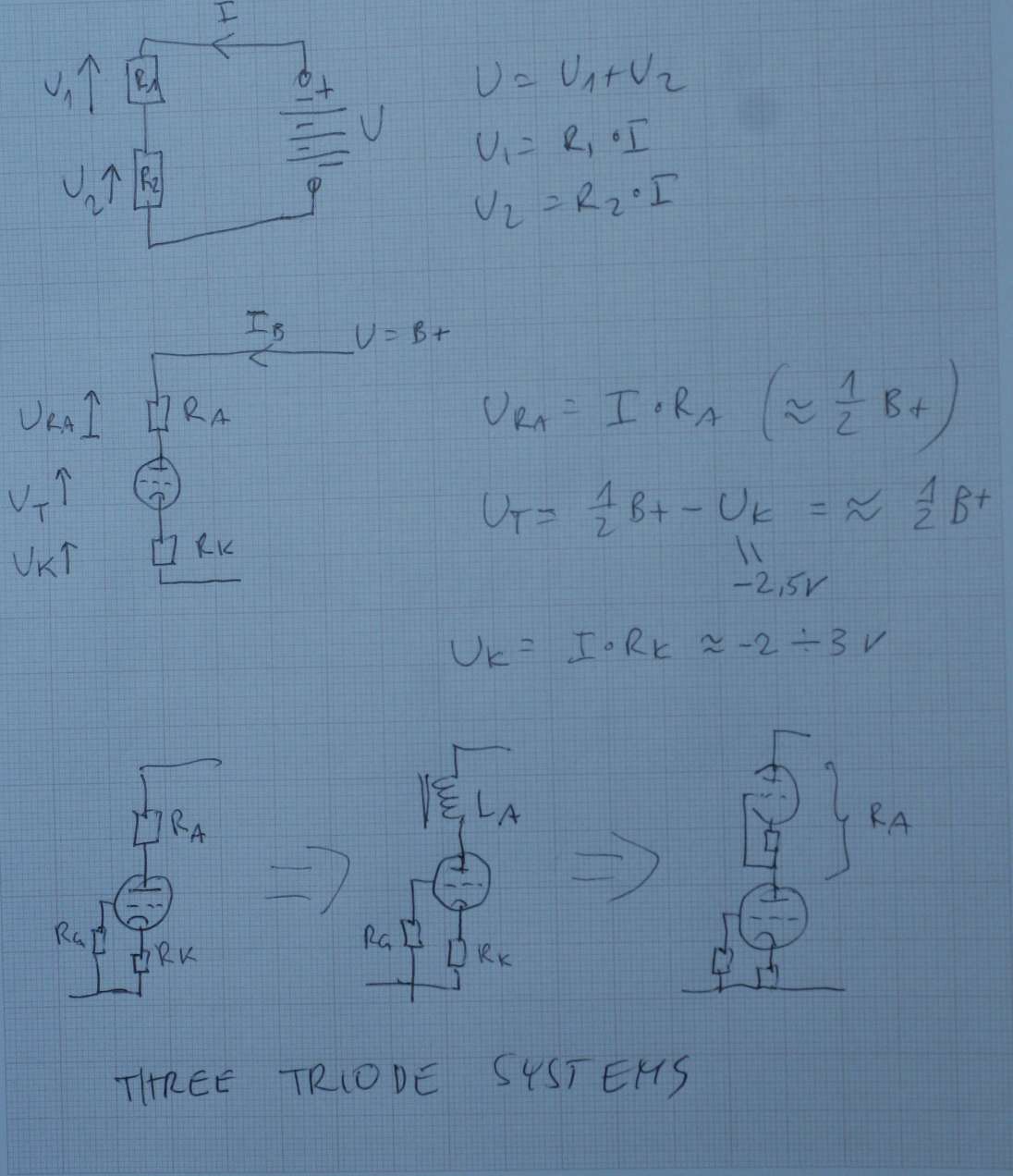
The whole tube current must flow via this resistor and by Ohm's law it
produces VOLTAGE DROP. The bigger drop the bigger resistor and the
bigger current.
U=I*R where U is the voltage drop on resistor.
Now there are three steps to design a triode amplifier :
1. Look on the datasheet of the tube at the curves and choose the
desired BIAS CURRENT. The area of the green circle is my favourite spot
on the tube curve drawing - see below.
2. Calculate that you want the resistor to drop to half of B+ supply at
the nominal bias current. R=0,5U/ I
3. Look again on the curve - at which grid bias value the 1/2 U and
nominal I will cross. This Ug must be lower than minus 2V, preferably
-2,5V
4. From Oms law calculate bias resistor in Cathode (cathode resistor):
Rk = 2,5V / I (nominal bias current)
We have all elements: Ra, Rk, Inominal, Ubias, - everything.
We can check if all is cool: lets check power dissipated by the cathode
P = U * I and it must be less than maximum triode specs.
I design for 0,4 Power Max.
Example:
We have 6H1P tube from russia, similar in parameters to 6SN7GT popular
in USA.
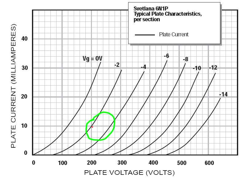
In green is the area where I design my triodes for lampizator and
preamps (amps are different story).
I try to be close to -2 or -3 area of grid voltage and not too high
with
current.
So here I choose the red point : 200 V on anode, 10 mA bias
current, -2
V on grid (bias voltage)
If we want to have on the Anode - after resistor - a half of B+ then B+
must be 400 V DC
Resistor will drop 200 V DC
Current is 10 mA so resistor Ra = 200V / 10mA = 20 kOhms.
Power of that resistor must be:
P=I*U = 200*10mA = 2000 mW = 2W. To be safe - we take 5W resistor here.
The cathode resistor is Rk = 2V/10mA = 200 Ohms.
The triode amplifier is complete.
Rk power is to be safe: P = I * U = 2V*10mA = 20 mW - it is neglible.
Any 1/4 W resistor will fit.
A notch higher level:
Choke loaded anode.
Actively loaded anode.
Choke can replace the anode resistor. The benefit is that the choke at
DC behaves just as a normal resistor. Just see - there should be R
given as a parameter on the choke.
If the current starts to swing, the choke behaves like resistor squared
- I mean - it resists MORE than a resistor. So the response of the
choke loaded triode to the input voltage swing is far greater output
response than with a resistor. Subjectively - that sounds more dynamic
- as it well should.
A good value is a choke with I max equal 2 x that of the triode bias
current, R DC of a few K Ohms, and L-inductance - of 20 Henries or
more, few tens of henries will be cool.
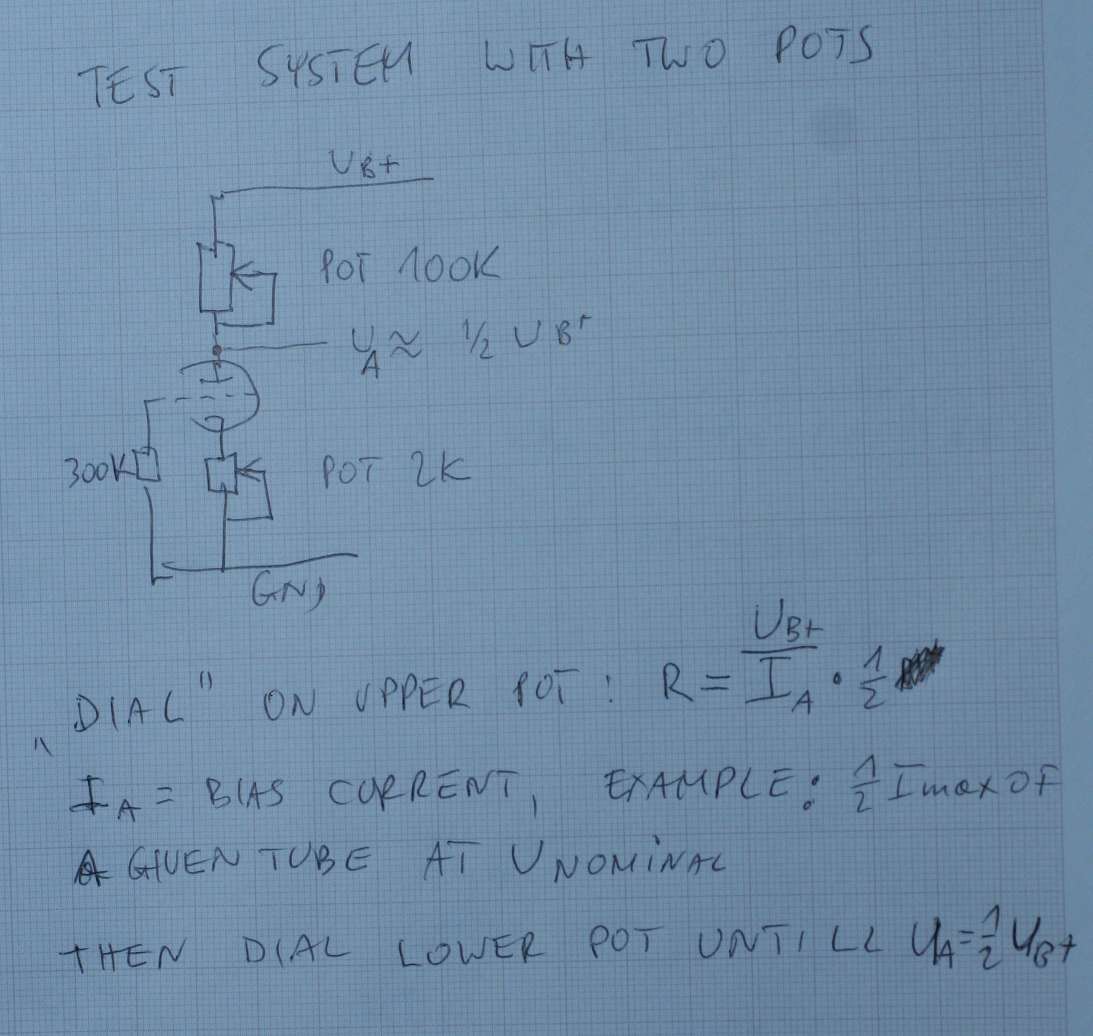
If you are not sure- in every case please use a 2 K pot in place of Rk
and connect the choke in series and "dial in" the desired cuttent of
bias. Then DISCONNECT the pot completely, measure it and replace withh
the nearest fixed R in your cathode circuit.
The SRPP or active load triode:
In this system we use instead of anode resistor or anode choke - a
triode which is configured to resist like a resistor - but again - a
resistor squared. The upper triode of SRPP is nothing else but a
resistor built from a tube. The feedback loop on the grid assures than
the more current we try to draw - the more the triode resists - and so
we get a standing push pull system. It is extremely clever.
It is the most friendly system in case of design errors - SRPP will
forgive you 50 % error in biasing etc - the upper triode regulates
itself. It is a dream system. it is also the system most immune to
power supply variations - so we can use DC unregulated. It saves us a
ton of work.
The voltage in the upper tube cathode should be always close to 1/2 of
the full powwr supply DC.
About capacitors: The input capacitor does not need to be large because
in the grid line current does not flow. Theoretically caps as small as
100nF are OK, I use 220 nF or up to 1 uF.
Their voltage rating can be as low as 6,3 V - common for oscons and
tantalums.
However the output cap should be trom the range of capacitance between
1 uF to 10 uF. Their voltage rating properly done should be the maximum
full peak value of unloaded AC secondary of the B+ circuit.
So if our B+ has 200 V under nominal load and conditions, chances are
that AC has 160 V AC RMS, so the rectified unloaded maximum will be
circa 280V. That is the minimum volt rating of the output
cap. Lets say - 2 x of B+ is a very good practice, B+ will be a
minimum rating ever, but NOT the voltage which is present at that point
during play.
It is enough that someone removes a tube, and due to zero current - all
caps will get 2x B+ voltage during the period of zero current.
Remembering, that in SRPP the upper triode takes half of available
voltage - we can design using the above described methods counting that
on lower triode - the Anode voltage is half of the B+.
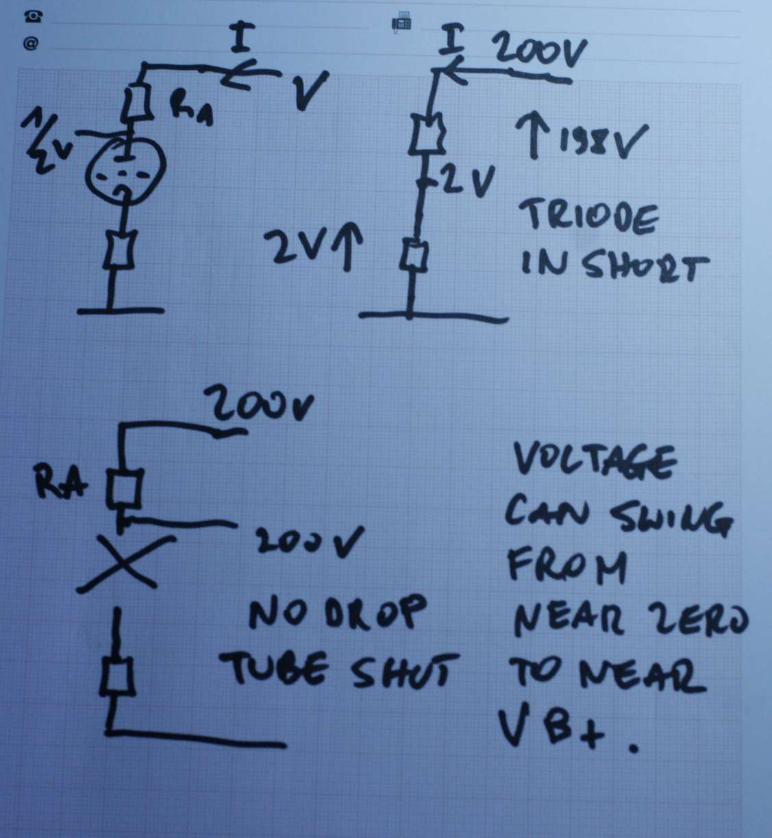
Tube as a switch
Of course the change of internal impewdance of a triode which depends
on the grid voltage is changing in linear fashion. But to understand
this simple circuit better - we can imagine the extreme example - tube
as a switch.
In resistor loaded anode follower, if the tue opens fully - it means -
it behaves like a short. In the circuit we have left the Anode resistor
and Cathode resistor.
The output voltage of the anode will be near zero - the flowing current
will cause all supply B+ to drop on the Anode resistor.
In the opposite extreme case - the tube will shut down and behave like
an open. The circuit will be open. There is no currennt flowing. So on
the anode there will be full supply - B+ because no current = no
drop on Anode resistor.