LAMPUCERA 1,0


NEW SUB-PAGE ABOUT MAXI-LAMPUCERA IS HERE

LAMPUZZERA LAMPIZZATA E BOXATA


CATHODE FOLLOWER PHOTO SESSION - QUICK GUIDE

OPAMP TWEAK IN LAMPUCERA MAX

Lampucera inside KEN CD player


This is my GEM found by coincident.

CS4397 DAC kit lampucera


The ultimate solution ?? Or is it ?
April 2 2008

After checking out what is going on inside all the CD players, my conclusion from just few MONTHs AGO was that I know what is going on:

"There are many different DACs, all are more or less Okay, and TDA1541A is the best".

Well, I was wrong. Not much, but wrong anyway.
There are better DACs, but quite rare, not that common to find in our regular players. There are no more CD players made today, so many of interesting DAC chips end up in expenceive PC sound cards,  or in DVDs, or SACD's
I looked for long time on the internet for tips which is the best, and I narrowed down my hunt to two chips. Wolfson DAC WM4870 is one of them but it is damn hard to find.

Then I ordered from Hong-Kong a custom DAC evaluation board, which has this great DAC chip - Cirrus Logic CS4397 which I currently consider to be the best there is, paired with the world's best receiver chip - Cirrus Logic (again) CS8416. Nothing more - just two IC's together on a smallish printed circuit board. All is a size of a credit card. Now I know that Cirrus is also called Cristal Semiconductors, I don't know which is their proper name. Now they produce the next chip - the CS4398 but it is not better for what we need it for.
Back to my board, this is a SACD compatible, DVD compatible, ultra modern and ultra fast 24 bit / 192 kHz format DAC, which also reads the CD redbook format of 16/44.

 
lampucera DAC lampizator

On the photo above - Lampucera is cleared of al low quality SMD electrolytic capacitors and awaits the capacitor upgrade. Note that there is no clock so upgrade is not necessary.

It has silly size, silly price, and my silly nickname to match, but seriously - if you want to end the search for CD source - your search is over. My search is over too.

The red dots are where we connect the lampizator - from top this is L-, L+, R+ and R-. I recommend to tap to the minus outputs.
The empty socket on the right is for output stage op-amp, which is removed now. If you put there a quality op-amp. the output stage is really kosher - one half opamp per channel and nothing more. Even without tube stage it sounds like a million dollars.
But with signal directly from red-dotted points - C27 and C30 - sounds better than from OP-AMP. For most people - this will be GOOD ENOUGH.

Two black chips on the photo are: the DAC and the receiver.
The silver cans are power supply electrolytes, we may change these
for Blackgates, os-cons, TEAPO, Jackon Low ESR and stuff  like that. You may also experimnt with tantalum caps - the result I havent yet tested but of course I will.

On the above photo - the electrolytes are de soldered and we may prepare the proper caps.
We need 8 electrolytes - larger in size than 47Uf and larger in rating than 6,3 V.
We also need 11 small foil caps.


All we need to add is a regulated +5V power so we buy a 10 VA transformer for 6 V DC, and put it through a zener bridge to a 10 000 uF/16 V capacitor and then through a regulator chip 7805 and then we add a cap - I suggest a 100 uF MKP not lytic.
Or we just order from Hong Kong the ready kit with a complete power supply.
Remember that 7805 needs a small radiator to dissipate heat. Without radiator - depending on supply voltage etc - the 7805's tend to burn easily. Even smallest radiator will do.


Lampization of Lampucera


We can connect this Lampucera board to any transport - any CD or SACD or DVD player that exists, and the output of the DAC chip has 4 signals - balanced stereo music signal. It can be used as it is straight from DAC to connectors, or apmplified by one op-amp of high quality, or connected directly to the lampizator.
I will call my adaptor DAC board a LAMPUCERA. The feminine "wife" of Lampizator.

If you want to stick to the OP-AMP - thats fine with me. Just upgrade the PCB of the analog secti
on with oscons or tantalums and use a GOOD OP-AMP - LM4562s . A nice person Richard Abdilla pointed me these great sounding opamps. I admit never trying them but I will.

The optimal combination of Lampucera and lampizator  will be that of a cathode follower triode. This schematic is extremely transparent, pure and simple. It has the lowest output impedance of all schematics - just 70 Ohms !!! Its gain or amplification is circa 1 so the DAC signal - which is on normal CD level 0f 2 V pp will be just OK.
Personally I prefer my signal to be loud and I would use the SRPP which I describe elsewhere, but many people complain that 10 Vpp is too loud for them. That really depends on the amp.
So for those who like to stick with redbook level - this schematics is optimal.

These plans are for DAC type VOUT and not IOUT. So this plan applies also to the Wolfson DAC. Other Vout dacs are not worth the effort.

SCHEMATIC 1 - cathode follower

Cathode follower calculations

CATHODE FOLLOWER PHOTO SESSION - QUICK GUIDE


SCHEMATIC 2 - Anode follower

Anode follower calculations

Also for those more ambitious - the Cristal DAC would play very well with
the Megalampucera: the board DAC connected to 6N13C triode amplification stage (megalampizator) just like in the Yamaha 480 description.


BUT  First - I upgrade it sans tubes.
There is not much we can "upgrade" about two integrated chips, but the power supply can be improved by removing or bypassing SMD capacitors (I hate them for their sound. SMD is a NO-NO in hifi world !!!)
and electrolytes - they can never  be good enough.


To evaluate the impact of capacitors - I created FIVE lampucera boards:
1. Standard as it is
2. fully upgraded by WIMA MKP and TEAPO lytics low esr shitty but cost effective caps.
3. As above but with the best OS-CONS - Sanyo caps regarded to be the best for digital.
4. Totally electrolyte- free "lampucera MKP" with 2,8 uF MKP's in place of electrolytes (crazy job - fitting these !!!)
5. Tantalum

I am able to connect them and A-B side by side to see which money is better spent.

Verdict is not yet ready !!! Hold your breath .


Tantalum lampucera - 33 uF / 35 V


tantalum lampucera

Tantalum (green heads )


Jackcon teaPO LOW ESR
Jackcon TEAPO low esr version with red WIMA bypass


os-con


Fully os-coned version


CAPACITOR GAMES

I was really very excited doing the capacitor games. Having ALL of thecaps on one PCB - all  of them  from one maker - should be finally AUDIBLE without a doubt. I wanted to nail down the characteristics of all these types.

First the easy one - the standard SMD type - on my subjective scale gets very low. There is no magic, no real high end sound.

The MKP type did not make it to the games - it will be evaluated in second games.

For the three other types the story is different.
All three mods rank VERY HIGH. Teapo, Os-con and Tantalum all upgrade the oryginal board significantly.

Now to tell the difference - I would have to be hard pressed except one.
To make the description easier - I will divide the criteria into 4 categories: Bass, Midrange and Trebles plus the Sensation of being there: respectively B,M,T,S

The Teapo gets in this context :     9, 8, 7, 7
The Os-Con gets:                            8, 9, 8, 10
The Tantalum gets:                          8, 9, 10, 8
and the naked untweaked board gets   7, 5, 4, 5

It is worth noting that:
each electrolytic capacitor has a SMD bypass on the board PLUS a red Wima cap 0,22uF/50V except the Tantalum which did not have the wima only SMD.
Teapo were 470 uF, the originals - 100uF, the oscons - 150 and the tantalums - 33uF.
Everything else was the same
Decoupling caps between the Lampucera and Lampizator were new chinese Obbligato PIO 2uF (FABULOUS !)
Digital signal was from Sony 557 ESD with KSA190A transport/laser.

The subjective feeling was that the trebles from Tantalum were so much superior to the other four that it was shocking. They were airy, pure, clear, strong, beautiful. Just the best I ever heard. But the rest of the spectrum did not match. The balance was tilted.

Os-cons on the other hand sound ..... like nothing at all. Equipment disappears and the musicians simply come to me. No trebles no bass - just total transparency and insight into the event. Quite spectacular feeling. I was amazed.
Teapo had very strong bass and everything else was really good. I could live with that. Considering its low price and good availability - a great value. MUCH above the standard board.

Now - any halfway intelligent reader would conclude at this point, that this could be the basis for MIX AND MATCH to achieve a 10 10 10 10 combination. Considering, that EACH CAP plays a DIFFERENT ROLE - I should be able to guess which cap should go where and what the result will be.
Well - you would be right. Thats what I am doing right now. If I could have the bass of teapo (I guess this is due to capacitance being so huge) and the magic of oscons, and the total treble power of the tantals. Oh My God !

I already made 4 test boards with the mixes and we will see.

In general - I would put the big teapo in the initial power supply delivery - say - in C19 (as marked by silkscreen not the schematics which says C20). Then I would bypass the smd small caps with a smallish Tantalum like a few uF instead of the Wima, and then - OS-CON everything !!!
That would be the ultimate recipe ala Fikus.

For the impatient people out there - if you want quick and straight advice - go all the way os-con. You cant go wrong with os-cons.  Tantalums may be interesting as an intelligently applied addition. Like spices in cooking. But  spices dont make a meal.


CAPACITOR TWEAKING EXAMPLE


lampucera DAC

Each SMD capacitor gets bypassed with a MKP - you can use any cap you find, I used Vishay 0,22 uF / 63 V which is also good for TDA decoupling. I do not remove small SMD caps - they can stay as long as they are bypassed.
I leave SMD in place - I am lazy.


DO NOT TOUCH THE circuit consisting of C22, C23 and R2 !!! This is a resonator.
Change the values if you want - foillowing the link for which I thank John Underhill:
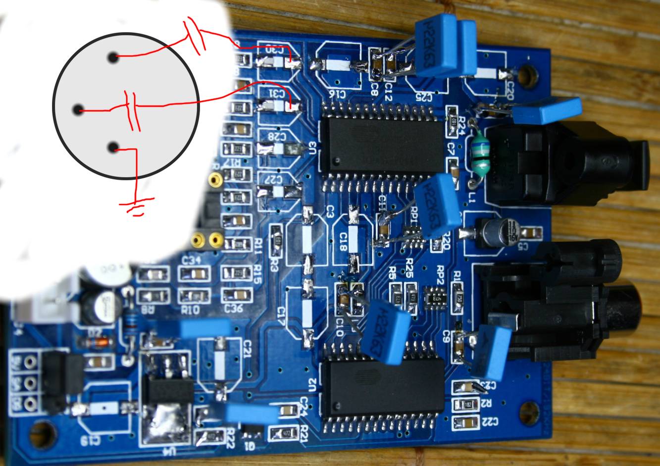
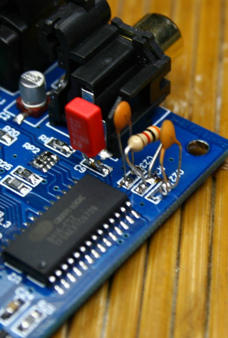
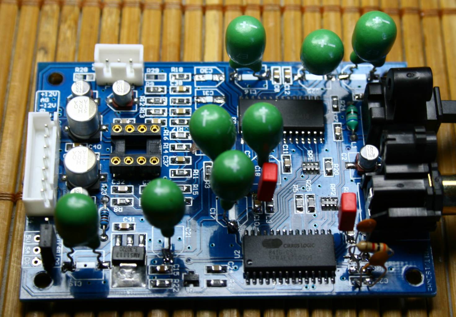
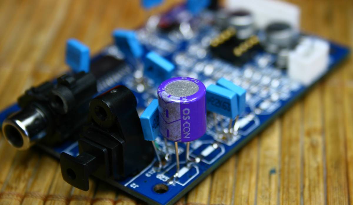
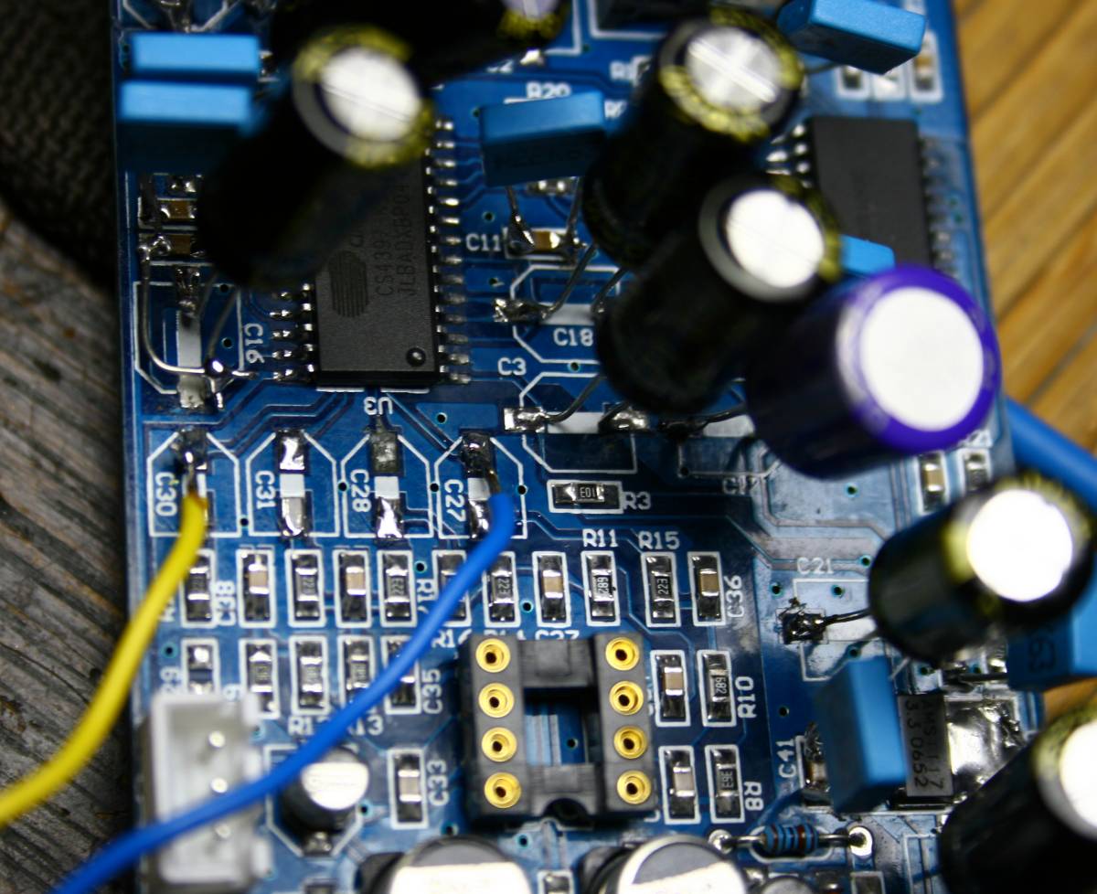
http://theartofsound.net/forum/showthread.php?t=315

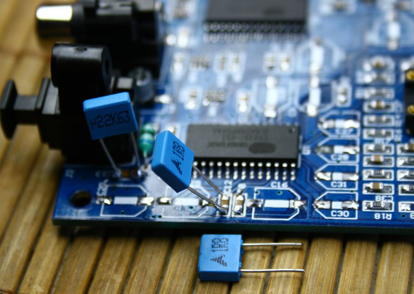
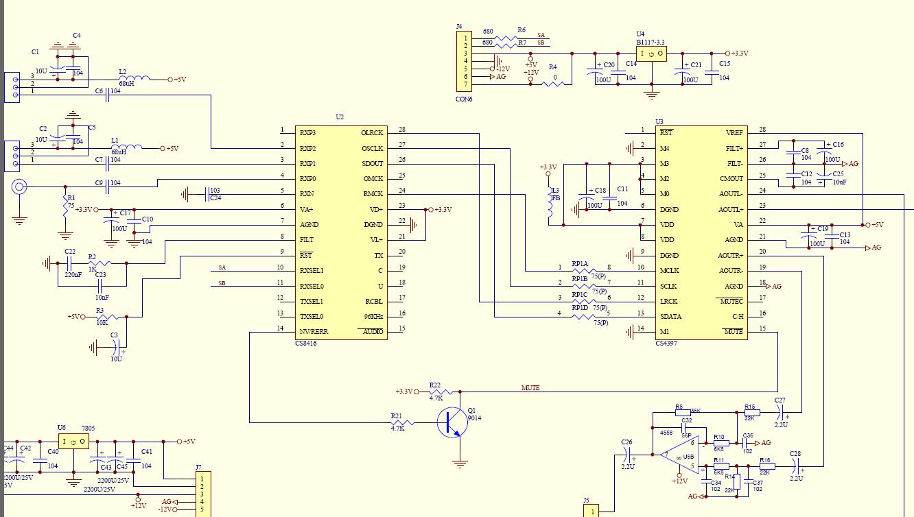
so R2 becomes 3k, C22 becomes 22nF, and C23 becomes 1 nF


Just like here:


Probably the long legs of these caps - at these huge frequencies - cancell any positive effect of the tweak. In reality the parts should be smd.


So first step - remove all electrolytes. Second step - bypass SMD caps. This will be impossible once the new electrolytes are added.

Third step: put new electrolytes - the type for digital circuits: I use OS-Con from Sanyo, and blackgates are good.
Size is unimportant - disregard what was on the PCB and inslall all the same size - above 47 uF and below 1000 uF, voltage min. 6,3 V , 10 or 16 V. (the power to the receiver cirrus is 3,3 V only, DAC takes 5 V)
Do not waste time on the caps for the removed opamp - these would be 16 V minimum anyway.


This corner cap is one of two most important ones. Power to the DAC.


The SMD all bypassed - most important are C9 and C10.


This big C17 oscon is critical for jitter - it sits in the RECEIVER chip power supply. C10 bypasses it for improved impedance matching.

IMPORTANT! The jumper goes CLOSER TO THE CORNER !!!


lampucera lampizator tuning

Less critical places - I used TEAPO caps not os-con.

lampucera

The tapping points for single ended operation. Of course - for balanced - would be all four points.


This is power supply. Plus is red wire, minus is black.
It can be taken from:
CD player motherboard - find the 5 V regulator (7805)
or a gel battery 12 V plus add-on 7805
or 4 cells AA without regulator
or a dedicated power supply
or find 12 V or 20 V on the motherboard of the CD player and add a 7805 to get 5 V. Add one huge cap like 2200 uF/10 V after the 7805.
Remember that 7805 needs a small radiator to dissipate heat. Without radiator - depending on supply voltage etc - the 7805's tend to burn easily. Even smallest radiator will do.

Don't forget that this ground (black) must also serve for signal minus.


Job complete


WARNING! The attached schematics does reflect the reality - only parts and connections - but the part numbers - are DIFFERENT from PCB silkscreen. 


TUNING TIPS:

these are from real PCB not schematics.
DAC:

leg 23 = L+ output - cap decoupling C31

leg 20 = R+ output - cap decoupling C28

leg 24 = L- output - cap decoupling C30

leg 19 = R- output - cap decoupling C27

c9 is digital input signal from RCA - in series - CRITICAL to use MKP cap of any value below 1 uF.

Power supply - legs 7 and 8 - plus 3 V - capacitor C3 and bypass SMD C11
Leg 22 - analog supply for DAC + 5 V C20 and its bypass  C13

leg 28 - reference analog - plus5V, also C20 and C13.

legs 27-26-25 - small MKP bypass on C12 and C8

RECEIVER CHIP:
leg 6 - critically low noise analog supply (jitter !)  C21, C17, C10 (MKP) Put your best blackgate here and o,1 uF MKP
Leg 23 gets the same supply as leg 6
Leg 21 - as above. 
C3 is unimportant (reset circuit) and it can stay as it is. It is the one NEAR R3 - it is marked on PCB in such way that it can be mistaken with C18.

ATTENTION: If you are using TOSLINK - it is critical to replace C2 which powers Toslink with something like generic electrolyte 330 uF / 6,3 V or larger. I used Low esr generic 2200 uF by 6,3 V. It improves toslink signal shape.


MAke the main power input caps LARGER, say 470 uF till 3300 uF. IO suggest to make the first cap - the power input before regulator 3,3 V (schematics C20, PCB silkscreen C19 )- larger  than the second one AFTER regulator - C21 which should be smaller. In my succesful test I used C19 2200 uF and C19 470 uF. If the second cap is too large, after switch-off the cap after regulator may discharge too slowly and eventually the regulator will be negatively polarized. It may burn.

The total tuning cost is circa 4 euros.
Without tuning it is also very good already.


DAC chip datasheet PDF CS4397


CS8416 RECEIVER DATASHEET

THE SOUND


The sound from LAMPUCERA is nothing short of phenomenal. Immediately it walks over any CD which I tried before. The transparency, the airy soundscape, the  details, the bass, the liquidity, the natural timbres - EVERY ASPECT of the reproduction is in a higher class than what I used to know before. With Lampizator it immediately creates the new reference category of quality.
And on top of that - the good news is that I love this sound, it is friendly and lovable from the first note. On every CD it excells. I just can't get enough of it. When I play my collection via LAMPUCERA, I just sit and turn my head in disbelief. How could such simple device be so much superior? So much better period? No exotic megabuck engineering, no sophisticated stuff, nothing like that. Just the wall of sound which nails me to the chair.
I stopped putting CD's to the boxes and back on the shelve. I pile them up on the table naked, pulling new ones and new ones.

The closest sound to Lampucera was coming out of the other CS chips - Meridian's 506.20 and 508.24, and from similar Zhaolu Dac 2.5C or 3,0.  Very lively, vibrant, open and analog-like sound. But LAMPUCERA takes it to another league.

Lampucera, with a proper power supply of regulated 5 V DC and digital SP/DIF input can be used as external DAC box. Or it can be hooked directly to digital signal inside the player. The output I like most is via a balanced megalampizator and it's mighty 6H13C tubes. It could also play from a SPDIF output of a PC, MAC or Laptop soundcard.

An interesting option is to use a battery (6 V GEL) to supply the board. People swear by this solution. Even a car battery with 12 V running through one 7805 regulator will be OK.

To learn about the ultimate quality of CD playback of LAMPUCERA against the World's best, please read my SHOOTOUT page.

I am happy to report, that I found the best solution for achieving the Hi-Fi NIRVANA of CD playback at a low price.
My board can be obtained as a complete KIT by circa 100 USD which is a laughable price for this level of quality !!! Not that I am selling it, but I know where to find it.

Search in EBAY.COM:

24bit/192KHz DAC DIY KIT , FULL ASSEMBLED KIT

Or just write here:

lawrencechanbig (a.t.) msn.com and ask for Lawrence. Tell him I sent you.

THE KIT:


I even tried it with a 5 Euro worth of used CD-rom as a transport with SP/DIF output (without PC, just on its own) and it played almost equally well as with a highend transport.

I just discovered that CREEK uses the very similar chip in almost all their players except the CD60 - which is another  superplayer with the single crown TDA1541A/S1 and MAGNIFICENT main board.

CREEK CD42 Mk 2

CS4328


CREEK CD43

CS4390

CDM 14 Sony

CREEK CD43 Mk 2

CS4396

CDM 12

CREEK CD50

CS4396

CDM 12

CREEK CD50 Mk 2

CS4396

DVD-ROM DVS DSL-710A

CREEK CD53

CS4396

CDM 12

CREEK CD60

TDA1541A-S1 – SAA7220P/B

CDM-4/14

CREEK EVO CDP

PCM1738

Philips VAM 1201


ENSEMBLE DICHRONO HI-DAC   CS4397

MARANTZ SA-12 S1           CS4397

MARANTZ SA-14              CS4397
MARANTZ SA-12S1
MARANTZ SA-13S1
MARANTZ SA-14
MARANTZ SA-15S1
MARANTZ SA-17S1
MARANTZ SA7001
MARANTZ SA8001
MARANTZ SA8260
MARANTZ SA8400

Data taken from :

VASILI's List of DAC chips:   http://www.vasiltech.nm.ru/files/cd-players/CD-Player-DAC-Transport.htm


Now concerning the upsampling frequencies: the board does not work as advertised. It works only with 44K !!!
Herre is a thread from some very kind members of DIY community discussing the issue. Apparently - the Lampucera PCB has a soldering error. Probably that's why they sell it without box and very cheaply.


jonners [Find more posts by jonners]


Offline

Location: Cheltenham

United Kingdom
CS8416/CS4397 board at 96kHZ? Post #1
I recently bought one of these cheap CS4397 dac boards from Hong Kong:.
It works fine at 44 and 48kHz, but at 96kHz I just get a hissy noise. I consulted the Cirrus Logic CS4397 data sheet and found that the mode operation settings on this board, which are M0=1 M1=0 M2=1 M3=1 M4=0, give 'single speed' (16 to 50kHz) I2S operation at up to 24bit. However, according to the data sheet for the Crystal CDB4396/7 Evaluation Board, these same settings give "Automatic Mode Operation'.
If anyone can help me understand what this means and suggest how to get it working at 96kHz I would be very grateful.
(The digital input, incidentally , comes from a Behringer SRC2496 upsampler. I've had it working with no trouble into other dacs.)


IP: Logged
New Post


error401 [Find more posts by error401]


Offline

Location: Vancouver, BC

Canada
I'm not sure where you're getting that from the CDB4396/7 datasheet, it seems to indicate the same values in the CS4397 datasheet, which is what I believe is true for this IC. The results you're getting make perfect sense given that schematic.

I would normally expect a DAC using this IC/receiver combo to utilize the 96KHz pin on the CS8416 to select a high sample rate mode in the DAC when you apply such a signal. An obvious failing of the design. M4 is the CS4397 pin that puts it in high sample rate mode, you'll need to disconnect it from ground and apply an appropriate signal.

You will need to carefully lift the M4 pin (2) from the PCB (or cut the ground trace), and bridge it to the CS8416 96KHz pin (16) with a wire. This pin is an output so shouldn't be connected to anything and you won't need to lift it.

Your other option would be to just lift the pin and connect it to a switch to choose manually. I don't see why you wouldn't use the 96KHz pin though, it's not really any more difficult and is more usable.

All of this of course relies on that datasheet being correct, but from a quick glance at it I think it probably is, at least concerning the pins we're talking about here.


____


New Post Yesterday, at 10:38 AM


jonners [Find more posts by jonners]


Offline


United Kingdom
Thanks for your help. I'll give that a try.

IP: Logged
New Post Yesterday, at 12:49 PM


jonners [Find more posts by jonners]


Offline


United Kingdom
Talking Post #4
Excellentissimo! All sampling rates now working, and 96kHz sounding very good. Thanks a lot for your help.


Here is the connection for balanced configuration of Lampucera:

lampucera XLR


it could not be simpler than that.
There are 4 signals R+, R-, L+, and L-.
First remove the 4 caps standing in the row which block the DC from DAC
Careful - because the tracks on PCB can peel off when heated longer than 2 seconds. Keep the soldering iron under 230 C.

Then add new caps - foil type - MKP or something, value 0,22uF (220nF) or larger, voltage unimportant. Solder them to the place after old caps, the position near the DAC.
Wire them to XLR - plus to pin 2 and minus to pin 3. Ground from PCB is wired to pin 1 of XLR. Just see the drawing attached.
Thats all. In balanced mode you dont need lampizator - the DAC is strong enough.  Although the lampizator output would of course be even better.


Lampucera inside CD player


BACK