The big
question of
TRANSPORT
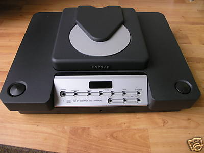
 Loewe 9000
CDM-ZERO wonderful machine
Loewe 9000
CDM-ZERO wonderful machine

In this article
we will touch a couple of sensitive points concerning TRANSPORT -
its role, quality etc.
1. Bits are
just
bits or aren't
they ?
2. Why
separate
DAC and Transport ?
3. What
sources
other than CD transport ?
4. Why do we
perceive quality difference between transports ? Why FIFO buffer a'la
digital lens does not solve all transport problems ?
5. How to
send
data? SP/DIF, Toslink, AT&T, I2S or other ? What makes
a link good or bad ? Does the word Digital Cable has
any sense at all?
6. Tweaking
of
our old CD player to make it good transport and a giant killer
7. Shigaraki
Clone Mania spreads like a bush fire
8. Can we
make
transports from old champions of mechanics like Philips CDM0 and CDM1
players?
Marantz CD 73 for transport, anybody ??? ;-)
9. Digital
outputs from NAIM, and Bang Olufsen 5500
10.
Oscilloscope
works on everything we can find about the SP/DIF
interface, cable and chips. Can we safely turn the adjustment head on
the SP/DIF transmitter transformer ?
12. What if there is no SP/DIF output (digital out) in our CD
player, only Toslink fiber optic type ?
The idea behind
transport and DAC being separate is that one can try
different DACs with his transport. Some people claim that the idea is
that separation per se gives improvement which is not true. It is a
myth. I believe in one box players because all parts involved in
musicmaking are close together and there is no problem. The separations
means that the signal has to go through three extra stages without any
benefit. If separation was an issue, we can do it by means of a simple
and cheap optoisolator chip. But two separate boxes mean that the
signal has to go to the transmitter chip, the transmitter interface
with transformer etc. and then through cable into a receiver chip and
so on. So there are many possibilities of screwing up the signal. I am
NOT CONVINCED AT ALL that separation brings any benefits, only problems.
Having said that
TODAY, 23 years after the best CD machines were
produced, we face the problem of laser failures. So separation gives us
an opportunity to buy or build THE BEST DAC money can buy and hold on
to it, and the transport - whichever we have - it can be a CD
transport, a CD player, a Playstation, a digital tuner, a computer, a
LAN receiver - can be substituted and changed.
So having a
super - cool DAC separately is not a bad idea. It will
serve us forever no matter what happens to the transport. If bits are
bits, meaning that if we supply the DAC with an information
embedded in ones and zeros - what makes one transport to sound audibly
different from another ? This is the key question. Some transports cost
as much as a Mercedes car and present extremely sophisticated means of
technical competence. Take the Air Forsell transport which suspends the
mechanism on an air cushion provided by medical oxygen pump. What an
overkill way of achieving nothing. Or is it ?
First
of all, let's agree that the digital SP/DIF (Sony-Philips Digital
Inter-face) has ONLY - I repeat ONLY - 4 factors of quality:
1.
Voltage amplitude
2.
Square wave rise time
3.
Timing precision
4.
Error correction - added data missing from unread pieces of
information. This is done by means of digital algorithm which adds
missing data by interpolation.
The first
factor
is least
important and it is dealt with by means of a
resistive voltage divider - two resistors which bring the source 5 V
signal to the proper 0,5 V pp.
The second
factor
has to do with
the cable parameter and transmitter -
receiver parameters. For example, the TOSLINK interface of red led is
not fast enough.
The only proper
way of sending square wave this fast is AES-EBU data interface - a
twisted balanced pair plus a shield in 110 Ohm line impedance and with
XLR plugs and sockets.
The third
factor
Low precisiomn
of clock timing causes errors called jitter and it depends on
the clock precision, cable parameters and rise time of the square. A
Signal slowly rising and slowly falling will have timing errors even if
the superclock with 2 ppm tolerances is installed. The CD players I
tried had the rise time equal to 1/3rd of the actual pulse width !!!
The fourth
factor
is the
most important one and the hardest to
correct. We have little influence upon how the laser reads scratched
discs and how the vibrations influence laser reading and how the chip
interpolates the missing bits. This is where the heavy transports make
a difference, isolation tables make a difference, mass loading changes
the sound, VRDS clamps make a difference, green pen, snake oil and
other tweaks make a difference. In general - the less error data
guessing the better. That's why a FIFO data buffers cant make the sound
perfect. They correct clock errors, jitter, rise time, signal levels
and all that - but cant recover the data lost and guessed - back in the
laser
reading process.
How is the
audio
digital data send from a CD player ?
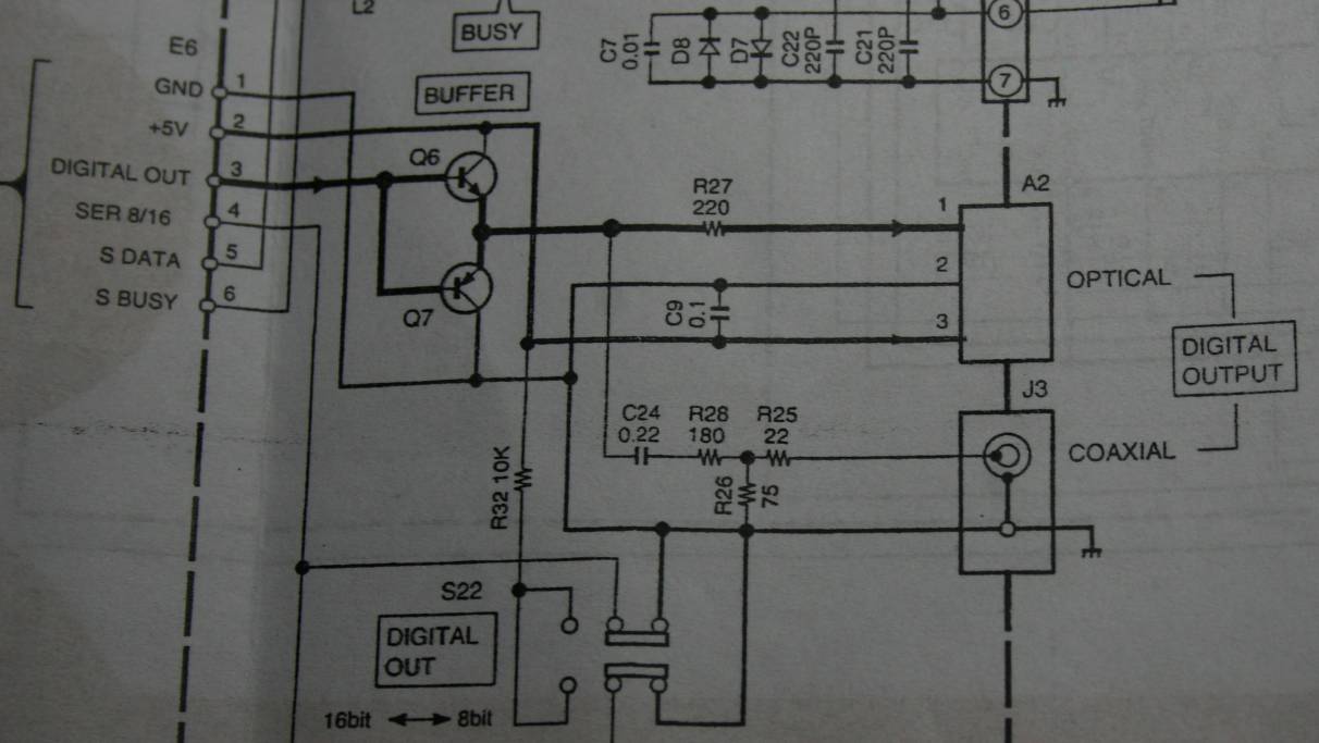
Well, in the
Philips machines the chip which produces the SP/DIF signal
is the filter SAA7220P/B. On pin 14th there is a "ready" signal.
Consequently in
all
machines which don't have the digital output like all NAIMs
and B&O 5500 we can get the output just by connecting the pin
14th
of the SAA7220 to the BNC or RCA digital output socket via a 75 Ohms
resistor with a series cap of 10-100nF.
This signal on
pin 14th of SAA7220 is 4 V pp so very strong. The factory
solution is that It is
sent to the output socket by means of:
- a capacitor
decoupler - 100 nF (ceramic is the best).
- a voltage drop
divider - in most players it is 560 Ohms and 610 Ohms
in series L-pad, creating a halving network.
On the picture below is a different divider as per SAA7220 data sheet,
but ALL players which I saw from Philips and marantz had the divider
560 - 610 ohms not 316-91.
I recommend in every player (even the one not used as transport): to
float (isolate) SAA7220 leg 14 and take the signal to output by the
antenna screened coax cable. REMOVE the noise associated with 5 V DC
switching sharply 2 million times per second from the PCB !!!!!!!

The above is from SAA7220 data sheet. I never found similar application
in real life, not even in Philips machines.
The output
circuitry and execution is
THE SAME on all Philips machines from the cheapest one like Marantz
CD40 to
the best Marantz CD94 MK1 and MK2, Grundig 9009, and Philips CD
960. If you need a transport - any Philips will do and will play
the same as Marantz CD7.
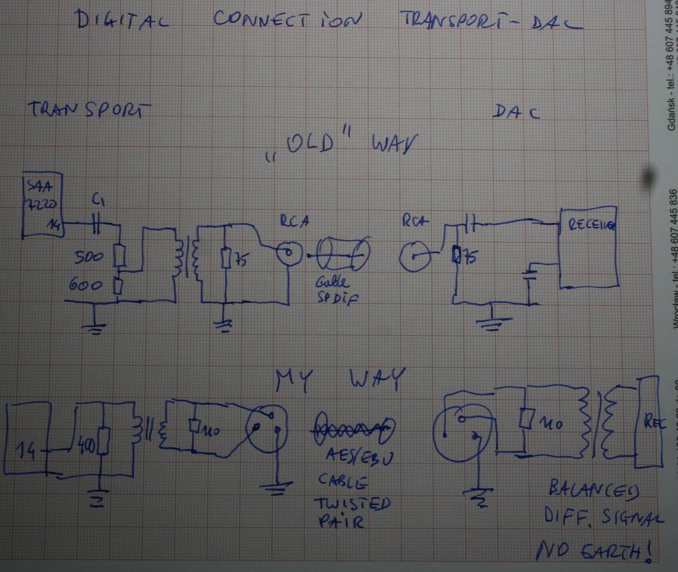
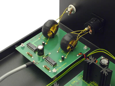
Then the
signal enters the separation and balancing transformer - a
small metal square can near the socket.
The transformer
isolates the signal galvanically and creates a free
floating balanced voltage source . Even if it is sent then by the coax
cable - the signal is not grounded so it travels in both lines -
center and screen - all the way to the DAC receiver.
It would be much
much better to install a XLR socket and send the
signal via XLR cable with tightly twisted signal wires. RCA is NOT a
good way of sending such signal.

This is from
Philips paper - description of the output.
Contrary to
popular belief, the TOSLINK is inferior way of
transmission. It has ADDITIONAL transmitter with own electronics and
LED light source and corresponding received with light sensor. Its
bandwidth is not fast enough to transmit the signal properly. The
TOSLINK interface is NOT USING the direct laser !!! it is a cheap
interface. It should be avoided whenever possible.
AT&T is
bloody expensive and not popular even if very fast and
accurate. The interface alone costs more than the whole transport.
The best way is
working on the player to get the signal from the output
balancing transformer and add a XLR female socket. The XLR cable can be
made of
CAT6 LAN cable with twisted pair connected to XLR jewellery of choice.
This will transmit the signal in balanced mode isolated from earth and
without any cable losses.
The SP/DIF
signal
is a 0,5 V pp square wave. It is VERY FAST. it
contains 44 kHZ of samples, each sample is a 16 bits, so it is 16
square impulses, and two channels alternating. So we send 2 x 16 = 32
squares per each sample. Plus some other information embedded like end
of word, and clock and checksum. So we have roughly 35 squares times
44,1 thousand = 1,543 million pulses per second.
From Furrier's
theorem we know that the square wave is an infinite sum
of sine waves of odd harmonics, so if 1,5 meg is our first fundamental
frequency, we need at least 10 harmonics to be represented
properly to make a square. This means that we need to send precisely
the sine wave bundle which includes clean 1st, 3rd, 5th, 7th, 9th,
11th, 13th 15th and 17th and 19th harmonics
The 19th
harmonics of the 1,5 meg is 30 megahertz. That is bloody fast,
as fast as radio waves.
It means that
there is a big demand on cable quality. What is cable
quality? Simply speaking, in order NOT TO attenuate the fast signal the
cable must have very low capacitance and inductance. So it must be
twisted pair with physical separation of wires and good low loss
dielectric. XLO way of twisting springs to mind. Twisted but quite far
apart. Third wire - earth - is sent by a separate third wire or screen.
The shorter cable the better. XLR made of CAT6 cable should be the best
DIY option.
IS2 interface is
an option which sounds superior on all equipment which
has this option. It makes the data slower, the signal is split into
three separate threads: actual data, clock and left-right word
separation impulse signal. So we need 3 wires plus earth to send I2S
but it is worth it. The SAA7220P/B chip has this format readily
available, as well as all receiver chips. It is usually done by means
of using computer 9 pin serial RS socket and a computer LAN cable.
TWEAKING
OF A CD PLAYER to make it a killer transport
In order to get
a good signal from a CDP we can address a number of
issues.
1. Vibrations
(mass loading, platforms, deadening, felt mats, sand
bags on the PCB, etc.)
2.
Mechanism supply capacitors - upgrade with low ESR and larger
sizes
3. Tuning the
output transformer - to provide the best square on
oscilloscope - just turn the centre core by a screwdriver or better
just remove the whole transformer.
4. changing the
series capacitor from transmitter side to be ceramics
5. Changing the
sockets from RCA to BNC or much better to XLR on both
the transport and the DAC while changing the resistor from 75 Ohms to
110. The secondary of the output transformer should be completely
floating and connected to XLR only and paralleled with the 110 Ohms.
6. upgrading the
cable to a low loss, low capacitance and low
inductance. 75 Ohms true wave impedance or better a AES EBU cable XLR
with 110 Ohms.
7. Installing a
super clock (after market) in the transport and in the DAC
8. Filtering the
AC supply by the RFI filter in both the DAC and the
transport.
9. Adding the
power supply capacitors like os-con sanyo to the digital
chips - the demodulator in transport, the digital filter SAA7220, the
receiver in the DAC, and the DAC chip itself.
Concerning the
drawing above: the saa7220 produces strong output of square wave which
we can modify by capacitors, transformer and resistors.
If we have an
oscilloscope with at least 30 MHz bandwidth, we can observe the signal.
The main thing is to observe it AT THE RECEIVER. It is the END RESULT
we are interested in. Not the starting point at leg 14th.
So we can for
example omit completely the CD player output transformer, it is not
critical, as long as the receiver at the DAC has a transformer (my
SATCH DAC has it). We can change the CD player resistor divider to get
stronger signal. or even go with full strength of 2,4 V.
The CS8414 and
8416 receiver accepts the signal as strong as 5 V so it is not critical
to lower the signal at the output to 0,5 V.
Any series caps
in the path are just to eliminate possible DC in the signal, but the
signal has no DC so we can omit the capacitors in the path in both
transmitter and receiver.
If we don't use
the XLR balanced twisted pair - we don't need both transformers at all.
The transformers
are always present in all CD players output. If we want to convert the
connection to XLR balanced, the transmitting side needs a transformer
with secondary winding completely isolated and connected to XLR pins,
and if the DAC has no transformer, we can buy an old CD player on ebay
for 20 Euro (defect one) and get the transformer from it. It is a metal
square can.
The resistors of
75 or 110 Ohms are not strictly necessary - they are just for
approximation of the cable LINE IMPEDANCE (WAVE IMPEDANCE or
CHARACTERISTIC IMPEDANCE) . The signal as fast as this is travelling in
the cable with the speed close to light, and the cable has a
characteristic impedance per meter, and if the receiving point has
different impedance - the signal may BOUNCE BACK and travel back and
forth as a reflection. It really behaves like a wave. When wave hits
the shore - it bounces back.
This causes the
receiver to go crazy because it sees more than one signal. It reads the
echo of the original.
So a good
practice is to use the resistor the same value as the cable
characteristic impedance on both transmitter and receiver ends.
Having said
that, the RCA connector IS ABSOLUTELY NOT a 75 Ohm impedance
connector., So no matter what cable, no matter what transmitter and
what receiver - the RCA will cause signal reflections.
The only good
solution is BNC connector (50 Ohms) or XLR (110 Ohms)
Let's not forget
that the resistor at the input is in parallel with the small
transformer. So in fact we see at each end not true 75 (110) ohms but
this impedance in parallel with the transformer winding impedance plus
the parallel impedance on the other side of transformer. So it is very
very hard to make a line with the same impedance as the transmitter and
receiver point.
Remember, it is
NOT IMPORTANT which impedance is at the transmitter or receiver. We
don't need to produce exactly 75 or 110 Ohms.
What matters is
that the IMPEDANCE OF RECEIVER, of TRANSMITTER and of CABLE WITH PLUGS
is the same. It can be 200, 143 or 59 Ohms. As long as it is the same
and it does not induce reflections and bouncing.
So in the end -
it does not matter what is between the source of the signal and its
receiver, as long as at the end we get the clean, sharp digital square
wave without reflections.
The last tip -
if you decide to keep the chinch RCA connection - just isolate the pin
which produces the signal - in case of saa7220 the pin 14, add a coax
cable with a screen to take clean signal all the way to the output RCA,
(not via PCB traces) and just divide it at the end near RCA by two
500/500 Ohms resistors. Omit all circuitry and the transformer, series
caps and original resistor network.
Of all the
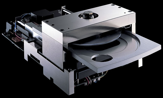
mechanisms which I know - the SONY KSS190A is the best for transport.
Or at least the Philips CDM1 not MK2. but MK1.
Here are
some
actual real life examples:

This is the
Sony
CDP227ESD :
as you see -
according to the red pointer arrows - the
signal comes first through the 33 uF electrolytic cap (it seems bad
idea anyway), then through the switch (who needs it ???) and then just
before the transformer we see a parallel RC network - 100 Ohms and 68p
Cap. This is grounded on one side of the primary winding by a cap in
series to ground.
On the secondary there is the expected 75 Ohm resistor, but wait a
minute ! It is in series, not parallel to the output. And the screen is
grounded via another ceramic cap. 0,1 uF.
The above is
is the
Kenwood CDP 7090 above
As you see the output is not passive, it has amplifier - two
transistors. They drive the output. The coax RCA has 0,22 uF in
series and a 1:10 divider of 180:22 resistor L-Pad. The expected 75
Ohms
is in parallel but the 22 Ohms - in series (reflection attenuator ?)
There is no transformer at all.

Above - this
is
Grundig
CD9009 SP/DIF output
This is an output I found in ALL Philips and Grundig machines
regardless of price or age. The signal is attenuated roughly 1:2
and then there is the transformer, no grounding, no 75 Ohm resistor, no
capacitor. Both transformer windings are simply grounded.
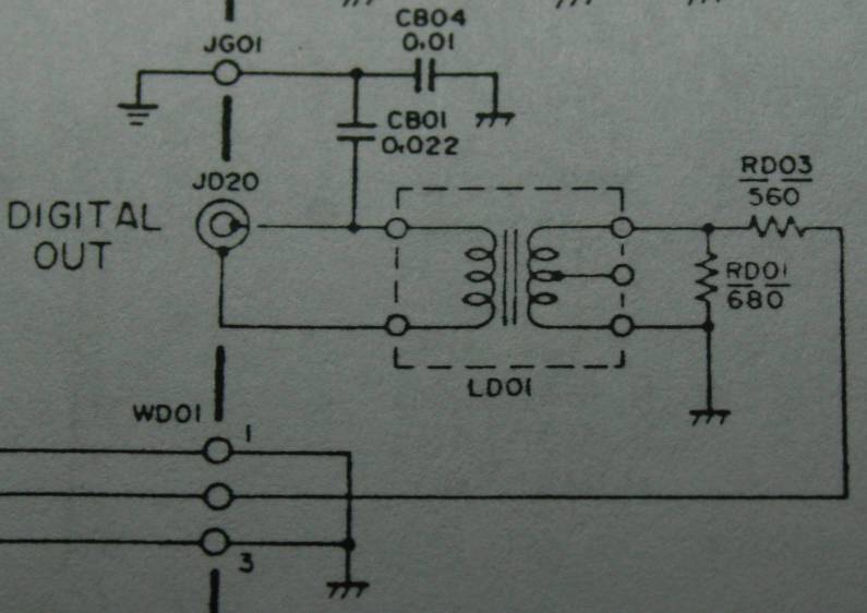
Same as above except that the re is secondary transformer winding
grounded via a capacitor.

The above is
Marantz
CD 94 MK1 and MK2 SP/DIF output
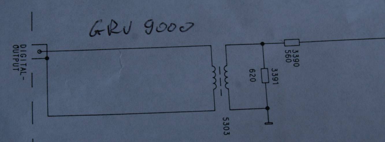
Above:
Grundig
CD9000
fine arts SP/DIF output

Above: Philips CD-753 SP/DIF
Output

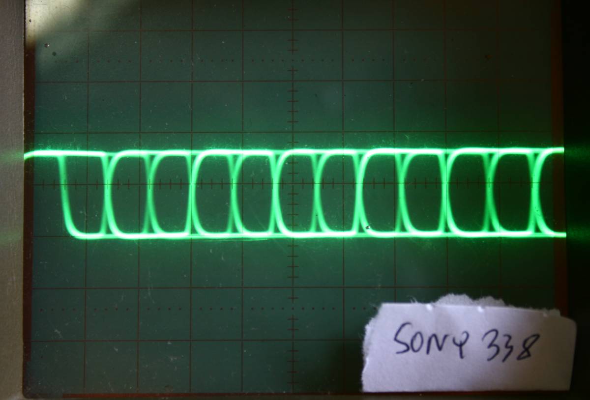
Above: Sony CDP-338ESD SP/DIF
Output
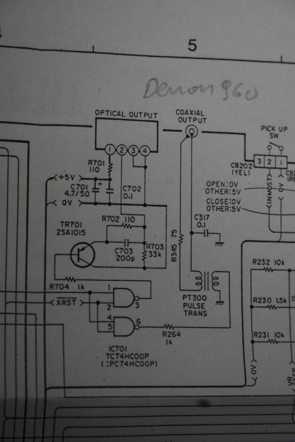
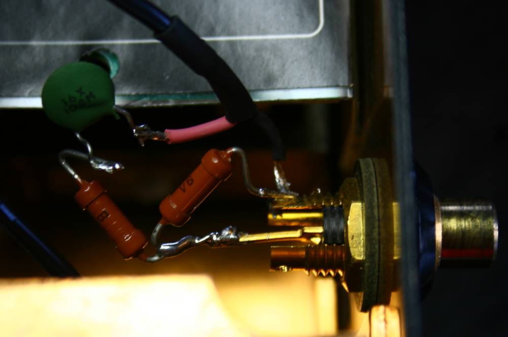
Above: Denon DCD-960 SP/DIF Output
Testing and experimenting
with SP/DIF
output of the
Grundig CD9009 Fine Arts player.
SUMMARY of what
we learned so far:
there
is no one proper way of doing SP/DIF (coax) but the most popular way is
the worst - with single ended coax transmission and wrong RCA
connectors.
The output
circuitry is different in every machine and there are no rules what is
best . You can try various approaches as per diagrams above - with a
cap, without, with transformer and without, with ground or without.
Observe the END RESULT on the DAC side - how good is the scope trace.
I discovered in
my Grundig CD9009 / SATCH dac combo that the DAC side RCA socket - when
externally grounded - improved the trace by VERY MUCH.
Whether it is
audible I dunno but I sleep better having it fixed.
The only proper
way of transporting the square wave is the twisted pair and balanced
connection via so called AES/EBU XLR cable. It is relatively easy
project - 20 minutes of drilling with 24 mm crown bit for XLR sockets
and 5 minutes of soldering the transmitter / receiver cabling.
Taking the old CD player to new level of CD transport perfection
In this section we will start to tweak the Grundig CD9009 to became a
good transport. It has all critical elements like good chassis,
screening, anti vibration arrangements, great power supplies, great
Philips CDM1MK2 mechanism, good servos, and a broken DAC section. So
lets see what it will take to make it a Theta / Wadia / Levinson killer.
To do this we need a fast oscilloscope (mine is 50 MHz) and a
"strong" drawer of resistors.
To be practical and stay on the ground - I will use typical RCA cable
and sockets on both sides and see how it can be accommodated to serve
as
proper transmission media.
I will look at the transport, plugs, cable, receiver and screening as
ONE SYSTEM, so my goal is to achieve good transmission as end result,
but he process can be freely modified. If it means for example
deviating from the norm and using a 50 Ohm cable, add two caps and
some spider web with bread - we will try it too.
1. Loading of the signal generating chip - SAA7220p/B on its pin 14
I observed no anomalies when the digital leg 14 of Philips SAA7220P/B
chip was unloaded (floating) or loaded with 1 K (as some schematics
above) or 300 Ohms, or even 75 Ohms.
I experimented with various caps in series with and the caps make
no difference at all. A 10 nF ceramic seems to be the best choice. Cap
or no cap - this is invisible on the scope so I decided to use it
because it seems safer (DC decoupling).
The trace seems sharpest and most elegant when the signal is coming
out of the SAA7220p/B without any transformer, just via one resistor 75
Ohms and one 10 nF capacitor.
This is THE BEST that I can get out of the Philips based machine. It
should apply equally well to thousands of CD players which use Philips
chip set.
Compared to original stock version - that trace is perfect !!! The
original trace was TOTALLY HORRIBLE !!! Probably due to poor
transformer.
The trace on the photo has been taken from the other end - the DAC
receiver chip. It INCLUDES in its shape - everything: the SAA7220
chip, the internal cable, the cap/resistor interface, the outgoing,
RCA, the 1 m cable, input RCA of the dac, internal cable, input 75 Ohm
resistor, and input DAC capacitors 10 nF.
The SONY chipset is
described below

2. getting from pin 14 to the RCA
I used a shielded piece of wire because this cable potentially is a
HUGE noise antenna. The 5 V pp of square wave at 2 MHz is enormous
emitter. Shielding is a necessary evil - it adds capacitance which
"rounds" the square.
MY LAST CIRCUIT THAT SOUNDS AND LOOKS GREAT:

3. Isolation of galvanic contact
I eliminated the transformer and used just capacitor as galvanic
isolation on both - transport and receiver side.
4. External cable - coax, telephone twisted pair or CAT 5 ?
On the scope there is little difference. The cable length
is
invisible,
while other nuances are very visible. Scope shows everything.
5. Receiver end - transformer or caps ?
Definitely caps. Just ceramic 10 nF or something similar. NO paper in
oils please !
6. Absolute level of signal
Please read the data sheet of your receiver chip. The signal is from
very wide range - starting at 5 V at the SAA7220 chip to as low as 0,5
V as S/PDIF norm suggests. The Crystal CS841* series tolerate as much
as 5 V.
I managed to arrive at: my schematics unloaded by DAC - produces 1,5 V
pp. After loading - it is 0,75 V. The signal locks every time.
7. Listening impressions
The modded system sounds better without a shadow of a doubt. The sound
is more crisp, better defined, with more background details. Good
recordings are now on the verge of hallucinations.
DAC used: Satch without digital input board.
Next, we will try the shigaraki clone transport - arguably the best
there is according to some people who know what they are saying.
Finally - who knows - maybe even a shigaraki digilampized will be made.
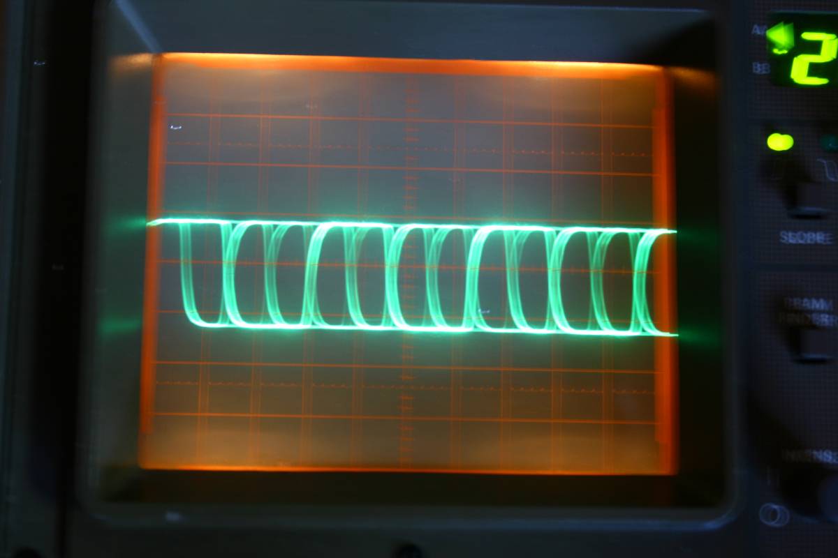
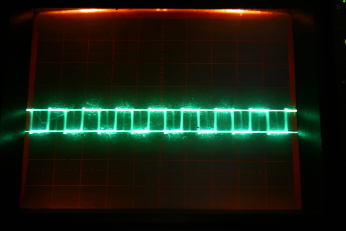
some other traces of SP/DIF signal
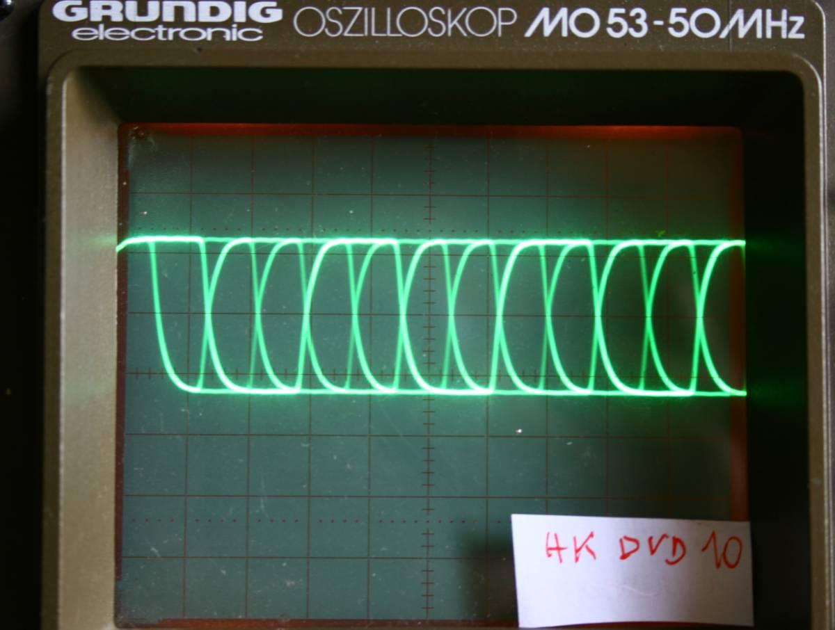
This is a middle price Harman Kardon HK DVD10 player - actually a
nice trace for such a plastic toy.
This excellent trace is produced by the Yamaha player - one of their
top machines with Sony laser and spinner. Model number CDX-890.

This is the Revox B126. Hmmmmm....
Wow ! Look at THAT ! Bravo Sony. Again and again Sony shows us how
things oughta be done. No wonder why - Sony player has a FET
transmitting buffer.
Thats why it does need any digilampizator to sound awesome on any DAC.

This quite nice signal is produced by the first and oldest and simplest
CD recorder - Philips CDR880. This first generation recorder has no
gimmicks - just 1x recording.
The recording sound quality is FANTASTIC. Much better that the Pioneer
model
05 that it replaced in my system.
The below is a nice trace made by Pioneer DVD used as a transport
aftert bypass of SP/DIF patth:
(READ ABOUT IT
HERE)
Nice trace ??
Improving the SONY chipset players
So far I was able to identify the SP/DIF on PHILIPS chip - SAA7220P/B.
With my patience and curiosity, I found the SP/DIF also on the Sony
setup. So far - only on one chip - CXD1125 leg (pin) 27. Or later
models - CXD1165 (also leg 27) Signal is called DOTX by Sony
literature. Since the chip
is an SMD type with thin legs - you must be careful to first find a
better soldering point - first after the chip pin itself. If not -
prepare yourself for microsurgery and THIN THIN soldering job.
Without any mods, the cd players from SONY higher models sound better
as transports than any other non-transport specialized machines.
I tried a bypass - from leg 27 to RCA, ar RCA add a 300 Ohms series
resistor and then parallel 75 Ohms at RCA . This mode sounds
significantly better than stock Sony. Improvement is audible - trebles,
bass, width, height, timbres - all improved without doubt. You can try
it and just stay with it.
Or do the digilampizator or digifetishizator
mod.
Digital Lens Phenomenon. It guides me closer to the TRUTH
about
transport sound.
Digital lens (it is a proprietary name of a product made in USA) is a
simple device - a data buffer. It is actually a fifo piece of RAM with
SP/DIF receiver and transmitter. It goes between the transport and a
DAC. It is supposed to improve the signal quality by recreating it from
scratch. Interestingly, The FULCRUM transport from UK
(excellent) has the
"lens" built in.
The data is stored in the RAM for a fraction of a second and so it is
"purified" of it's original sins. All history of the signal is
"forgotten and forgiven" and from the stored zeros and ones the lens
creates new data stream. It uses new clock, own generator of wave form,
so the new signal clone has no features of the old one at all.
The rise time is a result of new Lens' transmitter characteristics
The absolute signal level is created in the Lens
The timing (jitter) is a signature of the Lens
The data integrity is perfect - nothing is lost or added.
So far so good, isn't it.
Well, this is where going gets tough. We can accept for a fact that
most transports will be improved by the Lens. This multi-thousand
dollar (back in the nineties) product does a good job , better than the
cheap SP/DIF inside a given CD player.
BUT what is totally puzzling - why transports sound different via the
Lens ? Why we can tell one transport from another? Somehow a
signature of transport (like deep bass, wealth of details or smooth
sound) are smuggled through the process. From IT perspective this is
PURE NONSENSE but it is audible. I heard it when the Micromega Duo
mopped the floor with my digilampized Grundig - both via the Lens and
without it.
So there we go - I think that we found the truth about transport's
sound !
If it is not only the clock, not only the squareness, not only the
levels and rise time - there is ONLY ONE ANSWER possible and the answer
is INTERPOLATION.
There simply is no other possibility, the process is fairly easy to
understand and there is nothing mythical about it .
Bits ARE bits so if one musical piece sounds different from two
transports with ideal square wave, it means that the data is NOT
IDENTICAL.
Of course it is also possible that there is something else that I am
not aware of and INTERPOLATION is not the answer.
Another thought - When i change the output of transport player by means
of bypassing the last elements - I do not change data, I do not
influence interpolation - and yet the sound changes. It always
improves. So the quality is lost in the succeeding stages.
That proves, that the truts is somewhere else. Interpolation alone,
rise time, timing, jitter - are ALONE not the answer.
I was making a false assumption, that the CD mechanism picks pretty
much all the data. Only SOMETIMES, occasionally when the laser beam
hits a scratch or a blemish - the missing data is interpolated.
WRONG !
In computer world, all the data is always perfect, otherwise our bank
statements and excel spreadsheets would go bananas. If data is missing
on CD ROM - the computer recreates it perfectly from checksum, or if it
can't - it displays error message. Or a blue screen of death for those
unfortunate folks who did not yet switch to MAC.
The CD playback has no time, no computing power and no means (checksum)
to recreate missing data. So it averages the missing sample by looking
at the nearest good one. This is obviously not the real true
information.
If it was just one sample every now and then, say one per minute, that
would be OKAY. But what if the CD misses 30 or 50% of data?
It still plays, I mean if the interpolation works, there will be sound
even with 90% of missing data. We need at least two healthy teeth to
fix the dentures with 30 false ones.
So the sonic signature of a transport must be a combination of jitter,
squareness AND PERCENTAGE OF INTERPOLATED DATA. That answers why Lens
does not make all transports sound the same as it should well do.
A burned CD ROM with a text file is THE SAME whether it was created on
a
IBM, HP or Mac. It has NO HISTORY of the "quality".
That whole speculation, assuming it makes sense, and it does - to me at
least, also answers why transports sound different depending on the
table, the vibrations, the green pen trick, or the LED light addition.
Or say - why different BRAND of CD-ROM blank media sound different. Why
is Verbatim better than a noname.
My conclusion is: The amount of interpolation must be HUGE, it is a
secret of the industry but they read only a certain percentage of the
data, rest is ADDED by the solomon code CIRC chip.
(Later I found oyut that this assumption of mine was wrong. Most of the
CD playback is data-perfect.
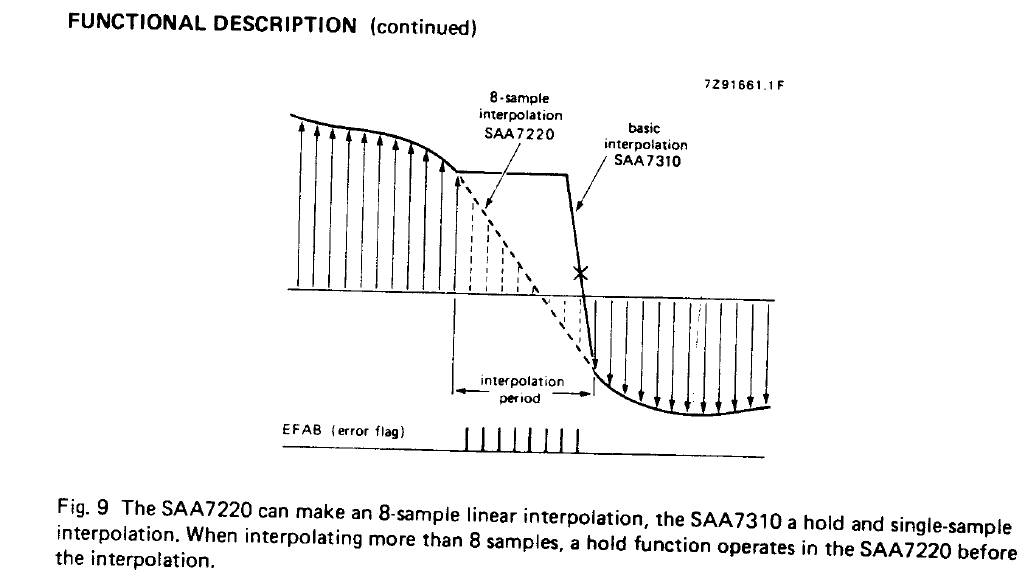
Below is the Philips explanation, showing the old way - SAA7210 and the
new way - SAA7310 demodulator and their respective ways of
interpolation of missing samples by filling up the silence with
approximate samples.
One consequent conclusion of that reasoning is that the good CD
player must be
really well made with attention to details: power supply, motor,
vibrations, servo, laser, lens, clock, transmitter, demodulator -
everything matters.
Second consequent conclusion (very interesting one) is that the perfect
transport would be if we could buy the music as PC file WAV and
play it from hard drive using just low jitter and "good squareness"
transmitter. That would eliminate interpolation process and we would
significantly get towards bits-are-bits perfection in data
transmission.
Going further - if we can communicate with the DAC via I2S format not
SP/DIF, we can get rid of the clock problem, jitter, and a lot of
squareness problems.
So a perfect transport theoretically exists, we just don't have it and
I can't
understand why.
A simple experiment which is too difficult for me would be to record
the data from transport on HDD and compare by computer the raw
data, not the music.
Just place the 1 second of a Pink Floyd song onto the excel sheet and
look at it like accountants do - like a balance sheet review. Or a Visa
card monthly statement.
I had once the Cambridge CD3 and it had a LED informing when
interpolation kicks in, and despite the CD 3 being otherwise a super
high end machine - the LED was always blinking with a speed of a
machine gun.
I am sure the LED was driven by one pin of the SAA7210 - namely
the pin 36 - ERROR FLAG. It triggers the interpolation. Just add a LED
to this leg with 1 k resistor and pull it to the front and try
listening. Then try the sandbags, potting soil bags, sorbothyane feet,
felt mats, green marker and parrot guano. See if it reduces the
blinking.
Maybe someone can design a RS232 interface to use PC as impulse counter
so we could actually see the number of errors per second. That would be
nice..
Crazy as it may sound, a friend of mine owns a nice transport and the
rest of his system is totally extremely revealing, and he noticed a
huge improvement when changing the power transformer on the transport
for a 100 times bigger one. The oversized transformer did something so
right to the sound of the transport that it left ten other transports
in dust.
The Fikus Interpolation Theorem" really holds in this case - the
transformer probably improved the reaction time of the CD spindle
motor, the arm positioning (tracking) and the laser focus motor. They
react faster to the commands of the servo controller. There is less
read errors and less interpolation. Not to mention squareness which
must be better too.
The walkaway message is that bits ARE bits,
providing we have all of them.
The walkaway message 2: The whole debate has been a waste of
time, we should get the I2S signal from the demodulator and communicate
directly with the DAC by I2S cable. And hence "bypassing all the
problems listed above".
A year later
A year later I am not closer to the truth. I have modified over 30
other transports, all in a carpet bombing fashion - improving
everything I can, to achieve something - I don't know exactly what.
The encounter with the CEC transport and the fact of it's didtinctly
superiour sound made me think again.
The whole CEC story can be summarized in one line: good sound is
achieved when we eliminate rotation variations of speed of CD caused by
the moror being non-linear and rotating in frog leap speed bursts of
the rotor versus stator. The flywheel plus weak motor are perfect
combination.
After modding 20 other DACS in their input receiver section I san
conclude that : One of the most important keys to good sound is ...
making the receiver chip imput HAPPY. By that I mean - that we must do
whatever it takes to make input be happy and play well. Be it signal
level, frequency, jitter, timing, squareness, rise time, cable
reflections, echoes, etc. Removing 74HC chips, transformers, opamps,
switches, caps, relays from both Transport outputs and DAC inputs -
greatly purifies the sound. So even passive components do make a
difference. Less is more !
What if there is no SP/DIF output (digital out) in our CD player,
only Toslink fiber optic type ?
well, if you have a toslink - you are a lucky person. It is as good as
having the SP/DIF. The toslink way of data transmission is inferior,
but not by much. You are welcome to use it as it is, providing the DAC
has such input.
But there is an easy way of converting the toslink to RCA or BNC output.
Just lift that PCB and look on the bottom side of the tosling
transmitter. It must have at least three legs: one is ground, one
is +5V DC power supply for the diode, and one is actual SPDIF signal.
The toslink uses red light as a way of transmission but the data format
is actually SP/DIF. Same thing!!!
So just take the signal from the data leg of the interface and wire it
to a newly installed BNC or RCA connecting socket. (drill bit 10 mm).
Dont forget to ground it as well. To be on a safe side - use a
capacitor in series of the signal - say between 1 nF to 100 nF - type
ceramic, foil, mkt, mkp, mks or even tantalum. If the signal seems to
overloiad the DAC end, it is possible to add a 75 Ohm resistor between
the signal and ground electrodes of the socket (RCA or BNC). This will
take care of the excess amplitude and adjust the wave characteristic
impedance.
The toslink may continue to work OK. The modd is easy, cheap,
innocent and reversible.
However be aware that Toslink traces like this :

That square directly from Toslink receiver is bad bad bad. It is a
miracle the DAC reads and understands this crap.
Known good transports:
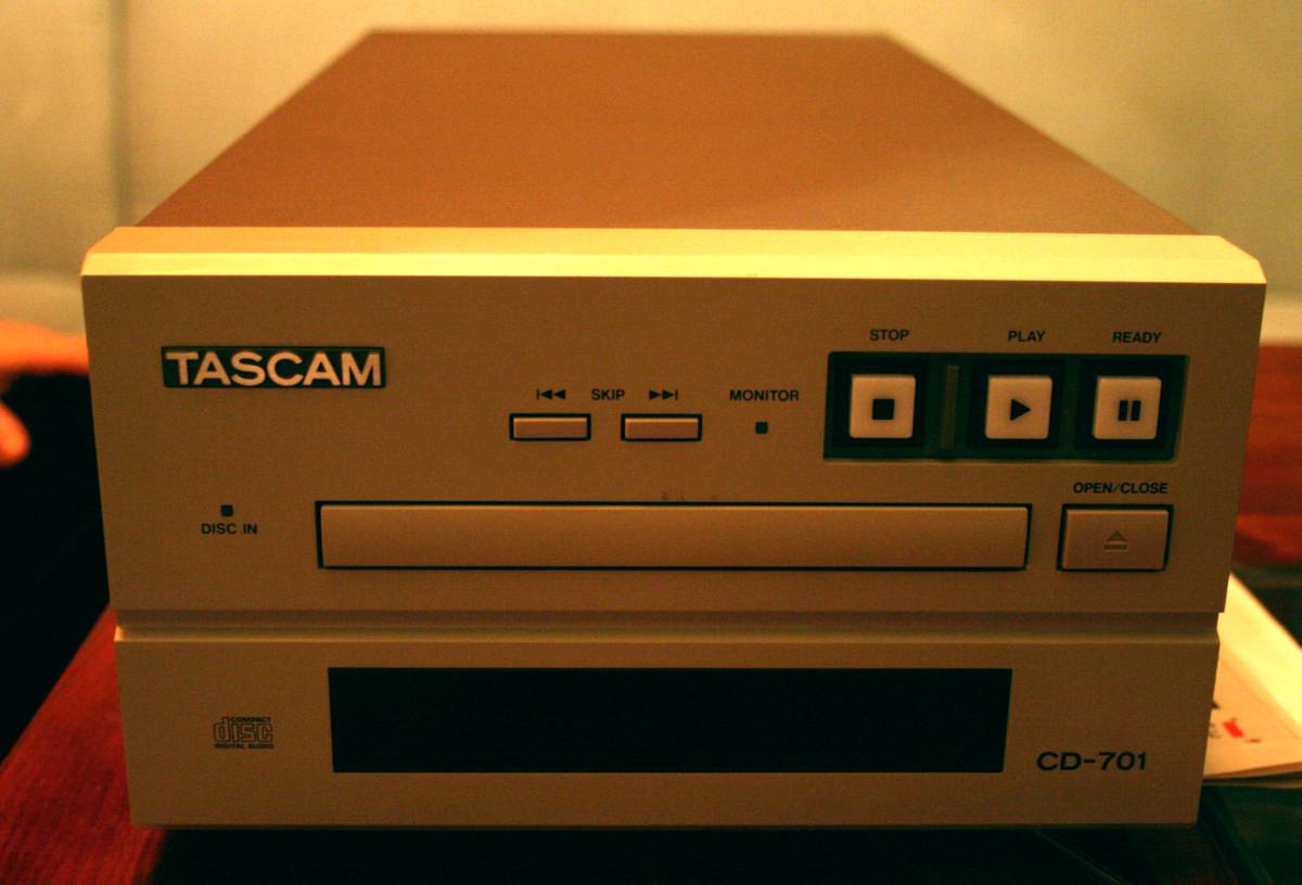
This is an example of an excellent transport machine - from a legendary
specialist - TEAC. They produced under their PRO label named
TASCAM some nice
transports for broadcasting and studios. Their mechanics were Sony
KSA151A with cast metal VRDS clamp and a wired remote, able to
control the timing of CD up to milliseconds.
I did not take the trace photo, sorry.
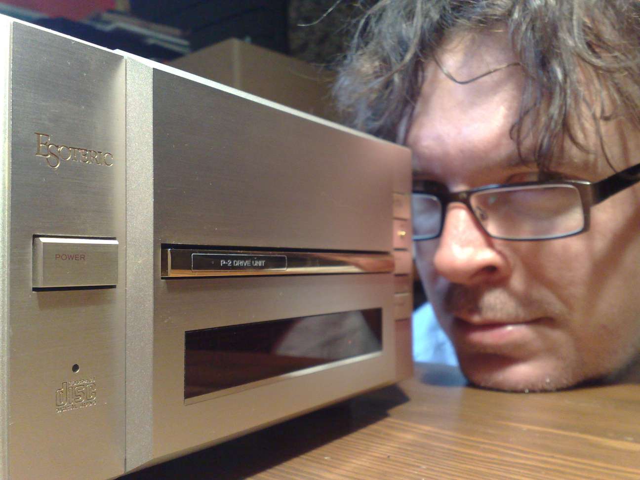
Below is the home version of the Tascam - its brother - Esoteric P2. I
mean the golden player is the brother - not my ugly face.
Audiomeca Mephisto (one of most analog-like sounding
transport)
Made in France by hand by Pierre Lurne - who knows something about
turntables.
Mephisto 1 has CDM9 from Philips, lots of shiny acryllic, home made
disc
clamp (light, wobbly and large) and a bad transformer for SPDIF.
Personally I love these players. They should come free as a bonus with
the
purchase of A-N DAC-4 or 5.
I review
Mephisto 1 here
and Mephisto 2 here
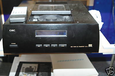
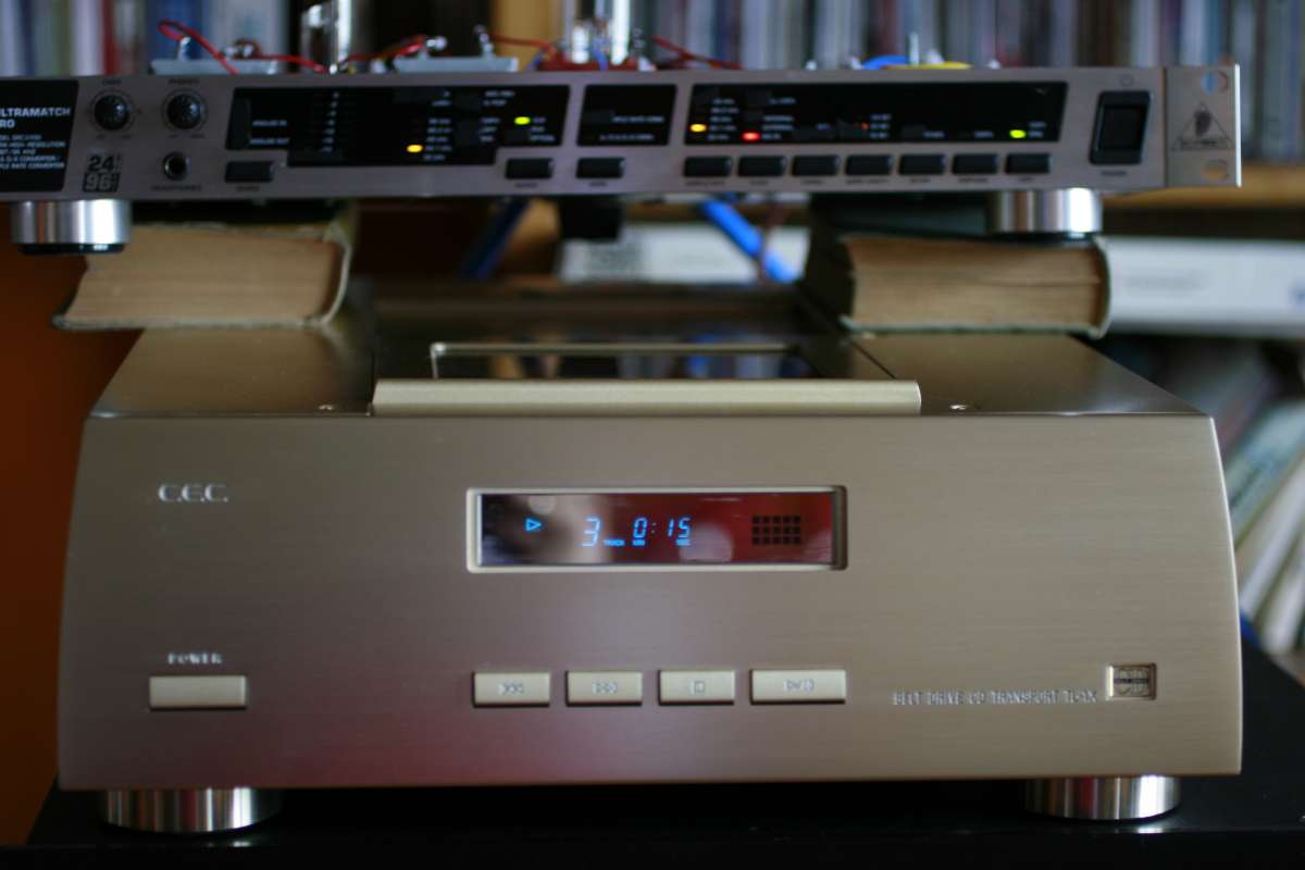
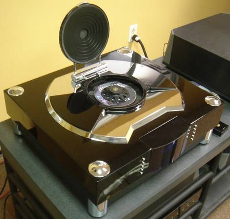
CEC TL1X (also under Parasound brand) (the famous belt drive motor)
Nobody is able to explain why the hell belt drive should sound better.
If you ask me - I think it's bullshit, just a very appealing
differenciator for
marketing. ( after I bought my CEC - I had to eat my socks and
apologize - the belt makes sens)
The CEC has been popularized by Stereophile and everyone including
yours truly wanted one a while ago. (Goldish one! please Santaclaus
!!!)
CEC may be good with belts, but they should learn more about the
aesthetics. To me this black box looks like Lenin's tumb, not an object
of desire.
Their TL0 - one modell above - looks great but the price tag has
printed message (next to the price) that says: whoever buys me must be
a drug dealer. (besides - the zero has same electronics as the one, the
whole price issue is about marketing and looks).
I review the CEC 1x here
Micromega Duo (with CDM9)

Micromega is a small French firm which had a distinct philosophy -
buying simple Philips players and refurbishing them up to a high
ticket.
The DUO is a stand alone transport with a toilet-seat-like lid, made of
acryllic and with a CDM9 mechanism.
Despite the fact that every time you want to change the CD you will
receive a 25 kiloVolt shock from statics, the DUO is very airy,
detailed and musiclal player. Somewhat similar to Mephisto
although the looks don't compare, even after a few drinks.
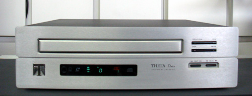
Theta (based on the Philips video laser disc)
I have written about the laserdisc principle in the laserdisc article
HERE
I also evaluated the Theta Data Universal
Mk2 transport HERE
The quality differenciator is the MONSTROUS motor which has 30 times
the torque of the standard CD spindle motor.
Thetas sound distinctly deep, powerful and they are a worldwide
reference for bass.
So I guess fast reaction time of the servo and all motors is
audible.
If I could hear it on a 50 Euro pioneer laserdisk, and believe me
- I heard the best bass too on this 5000 $
Theta. That's the HEMI V8 6,7L of the transport
world.
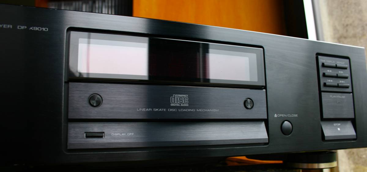
Kenwood X9010 (cheapest of the good ones). - best construction of
all
of the above
Read
about it HERE
Wadia makes good CD players and good transports, but make no mistake
about it - not THAT special. Definitely, apart from pride of ownership,
definitely not worth the money asked.
But I had to mention them because Robert Harley used to drool about
everything Wadia, as well as every other writer out there.
Apparently, cutting the most advanced cases for the products from solid
blocks of alloy pays. People are ready to buy the story and nobody asks
any questions.
Wadia (Teac transport with better case).
Same transport sits inside a
100 Euro Sony CDP227ESD, save for the clamp disk.
Ha!!!! Thats the real Mc.Coy. The best VRDS ever (not counting the Neo)
- note - the bridge is metal, not composite. It is shiny, not grey. It
is not a flat straight slab of alloy but curvy and ribbed. THATS THE
INDICATOR of the best variant. It was used only in 4 players in all
history at best.
PS Audio (engineered by fanatics)
Picture missing
In short - PS Audio is how the digital audio should be made, minus the
tubes at the end.
Roksan (unorthodox mechanically)
Roksan transport is very tempting, the Persian engineer behind Roksan
is a very interesting individual. I just missed the auction by a few
dollars and I was just THAT CLOSE to owning this wonderful rebellious
product.
Sonic Frontiers 3 with the "eye iris" lid
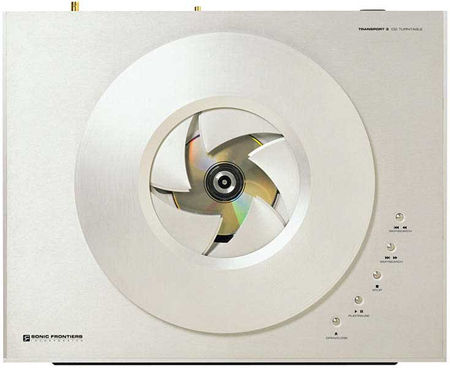
This transport, along with the Revox 426 could fight for the title of
the sexiest player ever made. Save for the handmade toys from Munich
High End show.
MBL made by people who do not care about cost
MBL from Berlin is famous for their "telephone number" price tags
and good products. TOTALLY TUBE FREE I must add.
Since I am not a German dentist, I have no idea how MBL sounds or even
looks. I never will.
People who own MBL are NOT the same people who say to me: Lukas, would you like
to lampize my player please ?!?
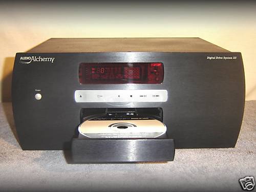
Some other transports worth checking: Shanling T200SACD, SONY777
SACD, Jadis, Accuphase, Shigaraki, audiolab, Rega, Audio
Alchemy (pictured below)
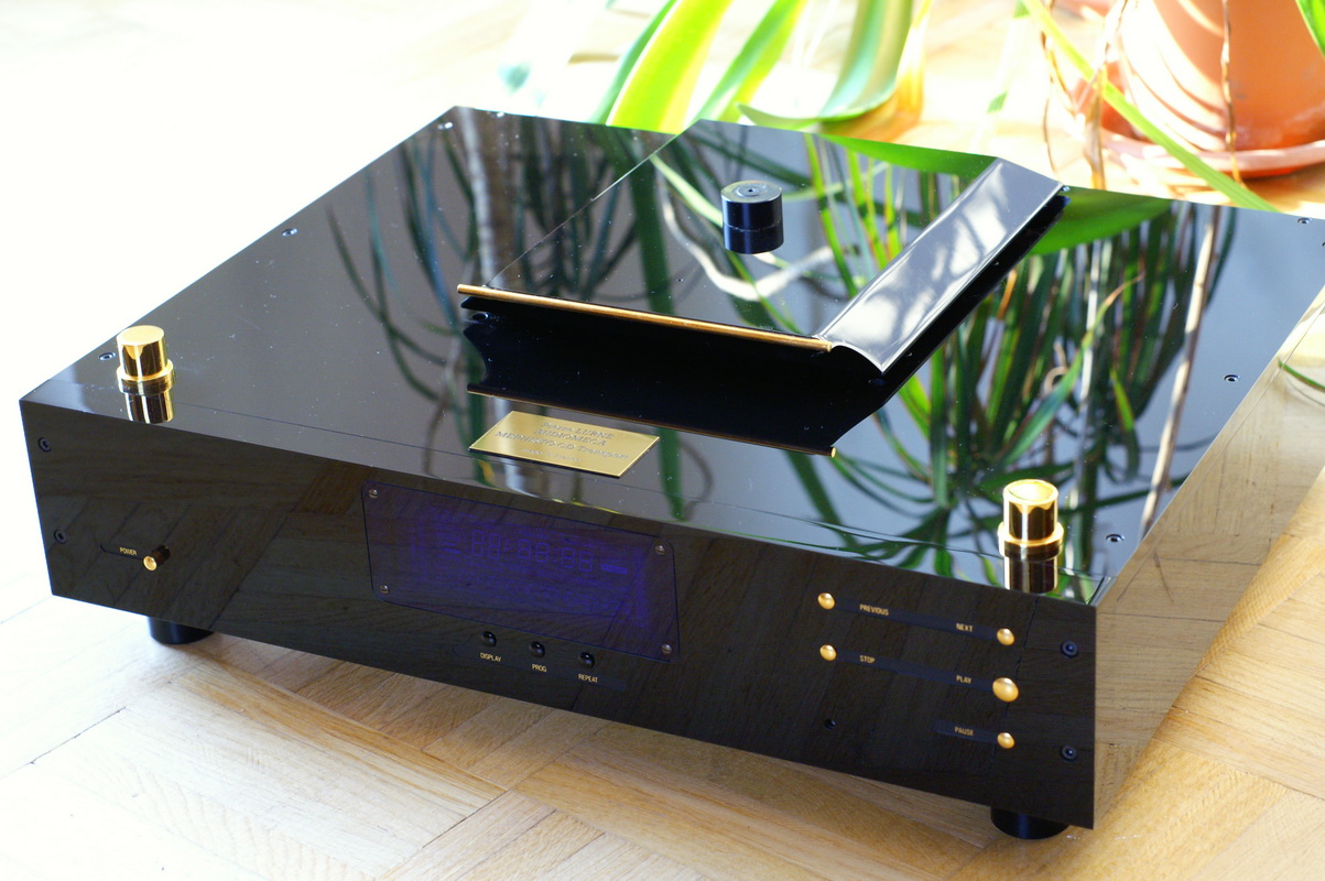
And now something really good: Audio Note Transport 2 - one of my
top picks!

This is actually the Philips CDM 2 PRO kit made properly.
This is my view
on teh CDM2PRO
And finally - what is believed to be the BEST TRANSPORT IN THE
WORLD - but not the bullshit kind like marble tumb, but real meaningful
honest engineering:
Spectral SDR-3000 from USA based on modified VRDS Esoteric
(teac/sony colaboration) transport.
Entrer TEAC NEO Mechanism
It is impossible to drool over the transport issue seriously
without mentioning the newest VRDS NEO from TEAC.
The NEO VRDS is the ONLY new mechanism made in many years. While the
whole world is going the MP3 way and DVD, TEAC decided to invest in a
"greenfield"
project of mechanism.
http://esoteric.teac.com/transports/p-01/
http://www.esoteric.jp/technology/vrdsneo/indexe.html
Frankly I am not too thrilled - what I see is the standard good
mechanism dressed up with 5 huge chunks of metal. This is hardly a
rocket science - but I am okay with that. A 5 kg weight is nice to
have, we buy by the eyes anyway. But asking 8000 Euro for it ? Thats
another story.
As I heard, management of TEAC decided that they will keep the
mechanism for themselves - they will not give it to OEM. They
want to keep price in stratosphere as long as the part of the market
which is a) rich and b) impatient - will be saturated. Then of course
they will change their mind and they will sell to every OEM that will
ask. I can bet that the price of VRDS players will drop 5 x in 2-3
years. But then dear TEAC it will be too late - the world will be
riding on HDD systems.
Meanwhile - I will stick to the real heavy weight champions of
mechanisms like KSS190, KSS273, and CDM1.
I lost my confidence in VRDS since I saw with my own eyes the bullshit
that they sell - as
described HERE
LINKS TO
MORE
INFO :
http://en.wikipedia.org/wiki/AES3
http://www.vandenhul.com/p_B02.aspx
SP/DIF
and AES/EBU explanation file:
DIGI-Lampizator
for the die hard diy'ers.
Stereophile
article by Robert Harley
Interesting
discussion 1
Interesting
discussion 2
http://www.diyaudio.com/forums/showthread/t-52357.html
- CDM1/2 experiments
LINKS TO
DATA SHEET - interesting reading:
LASER
LIST ONE
LASER
LIST TWO
SAA7220.pdf
Cirrus CS8414.pdf
You can read my transport findings - at the transport battle article
HERE
and here is again a link to my transport DIY project:
One year later - fall 2009
I have spent the free evenings worth of 2009 researching the
transports. I took different routes and finally a picture started to
emerge.
After all what was written above and elsewhere in my page, I can
conclude that:
1. There is nothing magical or mystical about the CD transports
(dedicated machines) versus CD players with S/PDIF output. There is
nothing that sets them apart except the fact, that the Transport is a
rare breed, hence it is addressed to demanding audiophiles, and there
is a potential chance to make more money. By removing the DAC and
analog stage from a CD player, and adding some weight to make it
look sexy - the price goes up 2x or 5x, depending how greedy is the
company.
There is nothing more to a transport versus CD - the same
mechanism as in equivalent player, then the demodulator chip (the
same), then the S/PDIF generating chip - Philips saa7220 or Sony
CXD1125. After that the square wave goes via a long trace or wire and
ends up in the output shaping circuit consisting of: a series cap
(unnecessary) , a L pad of two resistors (questionable at best) and a
separation transformer (unnecessary, cheap shit). Transports are
built the same way. The only improvement is that there may be more
vibration damping, better power supply (dedicated to the S/PDIF
function) and more attention to detail. But that same attention can
apply to CD player. We can do it at home to our Denon, Sony or Marantz.
2. I have demonstrated that by improving the power supply to the
digital PCB we can improve the sound. I modded this way the Philips
CD940 with great result, and then the Mephisto 1 - fantastic result,
and recently the CEC TL-1X - also great result. All these players
gained quality in every imaginable aspect thanks to adding
separate supply line (5V) per each consumer (chip) individually.
I dont like players where 5 chips, two motors, laser and servo - all
use one 5V source.
3. I am sure that a single ended connection is best for S/PDIF signal.
I do not like toslink and I don't like AES/EBU either.
The "pro" looking AES/EBU connection is using XLR and it looks OH SO
PROFESSIONAL WOWIE ZOWIE. We buy by the eyes. But the AES/EBU is
not invented to be better. It is invented to be LONG DISTANCE.
The RS422 industrial data transmission from which AES/EBU derives
can travel as long as 1,8 km (over one mile) on the twisted pair
balanced cable. The S/PDIF in coax cable can travel up to few single
meters. THAT IS THE DIFFERENCE. But the S/PDIF signal on both
ends exists ONLY as simple single ended asymetrical signal. We must
make it balanced artificially by means of adding a balancing
transformer which badly distorts the signal. Then we use in our systems
one metre cable (not one mile !) and we must use de-symmertization
transformer on other end again. That's two unnecessary transformers,
two too many for me.
In analog systems, the ballanced XLR has more meaning - as described HERE, but in
digital - the signal itself is never trully ballanced, it is the
sending media that is ballanced to make long distance possible.
so why is the AES/EBU sounding better on many transport/dac combos ?
Answer is easy. Because the S/PDIF on all transports that I have seen,
and I have analyzed about 40 different ones - is made wrongly and it
uses an ugly separation transformer as well. So in that scenario -
S/PDIF can not beat AES/EBU because they both have the biggest limiting
factor - the transformer.
That is leading me to fourth conclusion:
4. The digital output and input transformer is unnecessary and
can be disposed of without penalty or consequences. I tried it in every
player including the CEC, Mephisto, Theta and all - and every time I
had consistent result - increase of transparency, detail, scene depth,
improved bass and removal of veil. None negative effects were observed
so far.
That conclusion is explaining the AES/EBU phenomenon : in S/PDIF we can
remove both transformers, but on AES/EBU we can not. So a modified
S/PDIF beats AES/EBU. Plus - we dont need aes/ebu IN THE FIRST PLACE
because it is just a normal SPDIF with doubled up mirror signal by
transformer.
One may ask: Why is every manufacturer insisting on installation of
series caps and also separation transformers in CD player transport and
DAC and why is Mr. Fikus telling it is unnecessary?
That is a good question. When I ask others - what is the separation
transformer for? they answer me: it is there to separate. Separate
what? I ask - They say : to separate the grounds. Why ? Well,
because the grounds must be separated.
Then I ask: what is the capacitor for ?
They answer: son, the capacitor is there to isolate. Isolate what?
I ask...
Well, isolate noises or protect from spikes.
What noises? - answer is Digital noises.
So shortly speaking, nobody has a clue what to answer. NOBODY.
They are in the fog of stereotypes and meaningless talk.
This is the likely scenario how it happened.
Some engineers met back in 1982 in Eindhoven in the meeting room (as
the name suggests) and they decided that they want to move the DAC away
from the transport and that they want to standardize the format. But
they had no clue how to do it because they were audio analog engineers.
So the boss decided to call the guys from another department
downstairs - from data transmission department. They found Mike, the
guy who sends industrial controll and automation signals over the
distance. Mike knew how he does it for the transmission across the
factory grounds or the airport - he uses a transformer to separate the
grounds from one building to another. The potential difference between
earth in two buildings separated by few miles can reach huge levels. So
a transformer is a natural choice. The caps takes care of DC component
if any. So far so good. So mike decided he would recommend doing the
same in CD players. The CD player engineer greeted that advice with
applause , thanked Mike and the solution was wrtitten in
stone and thats how it started.
Then the followers copied what Phiips / Sony did without questioning
the solution. The transformer had to be there - full stop.
So I am telling you now - REMOVE THE TRANSFORMER. Mike was wrong.
Remove the capacitor and let the square be square.
You would not believe but any digital PCB - from CD player, computer,
playstation or another device has HUNDREDS of digital chips inside.
They have tens of pins each, and every pin may have a square data
signal, and these thousands of connections on that PCB are directly
talking to each other. AND THEY DO WITHOUT transformers and caps. Why
all of a sudden should 3 feet of S/PDIF connection need the same
precaution as the long distance connector ? I don't know.
Enough said.